Enter a street, stop name, or stop number to find real-time information. Choose whether you want to arrive or depart at the specified time. Select a route to view available directions and stops. Starline Track Busway is an open channel, overhead power distribution system that allows you to move and rearrange power when and where you need it, eliminating the need for electricians and minimizing. If three single-phase transformers are supplied by the utility to deliver power to the customer, a separate transformer tap has been designed for this application. This transformer tap is known as a “TTF” and is shown in Transformer Tap (Three 1Ø Transformers). If required, the factory can provide. ights, location and identification of each field connecti 1. 3 Orientation of plug-in units face in final installati and connection requirements for the system and accesso minum housing certified to serve as a 100% protective earth. Standard housing lengths are 1. May is National Bike Month, and there is no better time to dust off your helmet, pump up your tires, and. Don't see your stop listed? Plan to arrive at the stop or station at least five (5) minutes prior to the bus or train arrival time (all times are approximate). Rapid buses may depart up to five minutes earlier than the time shown, if traffic allows.
[PDF]
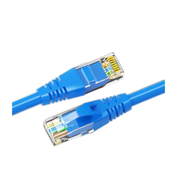
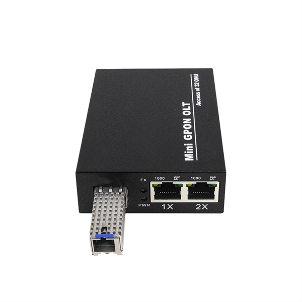
Yes, fiber internet requires specific equipment including an Optical Network Terminal (ONT) and a compatible router. The ONT converts fiber-optic light signals into electrical signals your devices can use. Choose a router made for high-speed connections to get the most out of your internet plan. Most fiber ISPs, including Mercury, provide an ONT that connects directly to your router via an Ethernet cable. This means you don't need a specialized. The short answer is no, you don't necessarily need a special router for fiber optic internet. However, having a router that is optimized for fiber optic internet can make a big difference in your online experience. Most modern routers are capable of handling fiber optic internet speeds, but they. Once the ONT and router are connected via Ethernet cable, the router creates a WiFi signal to connect your devices, or you can use additional Ethernet cables to connect your devices to your router. For the best performance, you'll want at least Cat5e or Cat6 Ethernet cables. Does Fiber Internet Require a Traditional Modem? The short answer is no. Instead, they typically rely on an ONT, which is short for Optical Network Terminal, or a fiber optic modem. These devices serve a similar purpose but function.
[PDF]
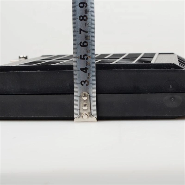
To install a floor box, you create a suitably sized cavity in the floor then place the box inside it so the lid is flush with the floor surface. You then connect the box to the cables that run under your floor.
[PDF]
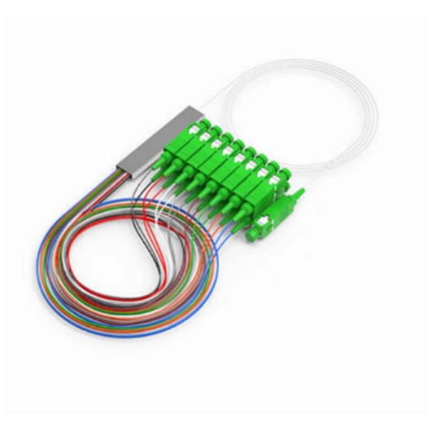
Use this worksheet to input values for all variables that will impact your system's performance. After entering your values, please ensure you click the 'Calculate Link Loss' button at the bottom of the page to generate your total link loss. Add connectors, splices, bends, and safety margin easily. See results instantly above the form, then adjust values. Choose a mode, then enter values and optional losses. All calculations use base-10 logarithms. mW must be greater than zero. Used only in measured attenuation mode. Length is needed. The power budget refers to the amount of fiber optic cable plant loss that a datalink (transmitter to receiver) can tolerate in order to operate properly. Sometimes the power budget has both a minimum and maximum value, which means it needs at least a minimum value of loss so that it does not. To detect whether the link runs properly, the following calculation should be performed. It is often the case to calculate the maximum signal loss across a given fiber link during optical cable installation. First, you should be aware of the fiber loss formula: The Total Link Loss = Cable. Therefore, it is very important to calculate the fiber loss and take appropriate steps. In order to get the most reliable results, an Optical Time Domain Reflectometer (OTDR) trace of the actual fiber connection should be completed. This will provide you with the real.
[PDF]
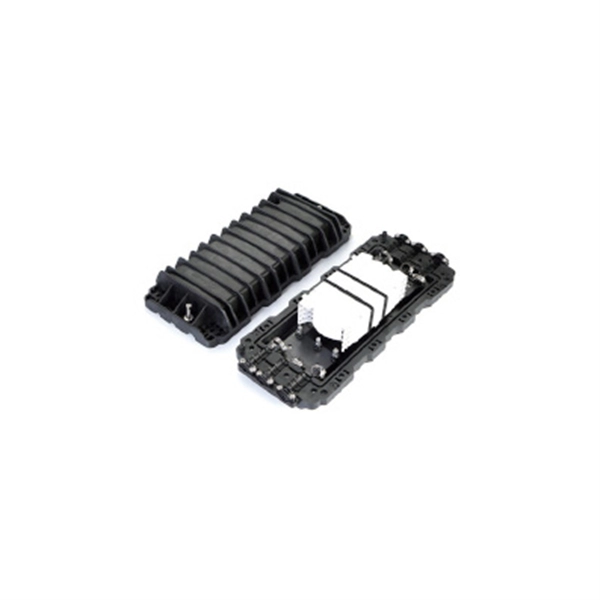
The cost to fix a fiber line often hinges on the fault type, distance, and response time, with price ranges reflecting differing crews and materials. Includes crew time for fault locating, splicing, and testing. Includes connectors, fiber patches, splice. Buyers typically see repair costs driven by cable type, damage location, and access challenges. Includes crew time for fault locating, splicing, and. This guide provides a detailed roadmap for locating and fixing fiber optic cable breaks, covering detection techniques, repair methods, and best practices. With CommMesh's advanced tools and solutions, you'll learn how to restore networks seamlessly. Main cost drivers include on-site labor, specialized fusion splicing, testing, and any necessary restoration of network performance. This guide provides practical cost ranges in USD with. Fiber optic cable is the primary media for outside plants, campuses, and LAN backbone infrastructure because it can transmit more data farther. It also comprises the majority of data center switch-to-switch and switch-to-server links that transmit high volumes of data at faster speeds. It's even. When fiber optic cables fail or require maintenance, typical repair costs hinge on incident location, damage severity, and the required equipment. Expect costs to reflect both material needs and labor time, plus any regional price differences.
[PDF]
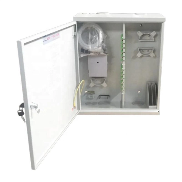
In this video, we'll walk you through the process of wiring a home distribution box with a detailed connection diagram. Whether you're an electrician or a DIY enthusiast, this guide will help you understand the basics of home electrical distribution. What is. In this video am going to show you how you can simply repair your electric flat iron with connection guideline in video above. Choose the right box based on environment (indoor/outdoor), load capacity, and durability. Check for proper IP/NEMA ratings and material quality. Ensure safe placement: install in. An electrical panel box, also known as a breaker box or a distribution board, is a crucial component of any electrical system. It serves as a central hub for distributing electricity throughout a building, ensuring that power is delivered safely and efficiently to all the required locations. It shows us all the parts that make. Setup of the distribution board is based on a 3-step principle (wall pan / mounting insert + DIN frame + door) Complete types incl. neutral and protective-earth screw type conductor terminals 33 1MU devices / row. Only for indoor applications. What is Distribution Board? Distribution board.
[PDF]
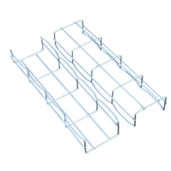
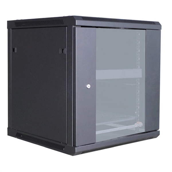
This guide discusses common cable tray problems, from loosening and corrosion to grounding issues and installation errors, along with strategies for prevention and resolution. Understanding the root causes of cable tray failures is the first step toward ensuring system reliability. Let's delve into. Steel cable trays form the backbone of organized and efficient electrical wiring in industrial, commercial and infrastructure projects. High-current power cables placed close to sensitive control or communication lines also help to cause heat generation. Refer the below link: How to do the voltage drop calculation of instrument cable? How. The entire cable line is completely burned or one of the phases is damaged, causing all the current relays on the distribution cabinet to activate. The damage at the fault location is extremely severe. Short circuits occur in all phases of the cable, which will also trigger the interlocking. The cable trays aren't connecting no matter what angle I try to connect them and I am presented with the following error message in the image attached despite loading all the cable tray connectors. At first I thought the angles were perhaps too much for the software to automatically connect but. There is no restriction as to where the cable tray system is installed. All metallic cable trays shall be grounded as required in Article 250. 96 regardless of whether or not the cable tray is being used as an.
[PDF]
For each laptop, PC, or game console in the setup, you shall connect both their video out and USB port to the KVM switch. For each system, the ports are grouped and numbered. Put each cable in the rig.
[PDF]
Busways, or bus ducts, are long busbars with protective covers. Rather than branching from the main supply at one location, they allow new circuits to branch off anywhere along the busway.OverviewIn , a busbar (also bus bar) is a metallic strip or bar, typically housed inside,, and for local high current power distribution, transmission, or switching s. The busbar's material composition and cross-sectional size determine the maximum current it can safely carry. Busbars can have a cross-sectional area of as little as 10 square millimetres (0.016 sq in), but. • – Data transfer channel connecting parts of a computer• – Low resistance electrical conductor for high current transmission and distribution• – Modular approach t.
[PDF]
Experience seamless internet connectivity with the Xiaomi Mi Wireless Router 4C. Designed to deliver wireless speeds up to 300Mbps, it ensures smooth streaming, gaming, and browsing for your home or office. Dual-band offering 3570 Mbps wireless speeds*. Paired with the 5GHz band, 2x2 MIMO and 160 MHz, unleash the full force of Wi-Fi 7 and experience network speeds beyond your imagination. *3570 Mbps is the theoretical maximum wireless rate for dual-band concurrent 2. 4 GHz and 5 GHz connections. Fast & Free shipping on many items!. LAN Data Rate: 300Mbps Global Version Xiaomi Mijia WiFi Repeater Pro Amplifier Router 300M 2. 4G Repeater Network Mi Wireless Router 2 Antenna Home ● Two powerful high-gain external antennas give wider coverage and better performance ● Wireless function, make your wireless coverage larger ●. Carbon emissions from the lifecycle of this product were measured, reduced and/or offset. The ClimatePartner certified product label confirms that a product meets the requirements for the five steps in climate action including calculating carbon footprints, setting reduction targets, implementing. Updated by Timo Altmeyer on the 1. October 2024 The Xiaomi WiFi Router 3G is a continuing model of the 2016 released Xiaomi WiFi Router 3. What innovations the router has to offer and how it beats in practice, more in this review. Equipped with 4 omnidirectional external antennas, it provides wide and stable Wi-Fi.
[PDF]
Fibre Channel is a high-speed network technology used to connect server to data storage area network. It supports data backup and replication. Fibre Channel is needed, as it is very flexible and enables the. Fibre Channel (FC) is a high-speed data transfer protocol providing in-order, lossless delivery of raw block data. Fibre Channel networks form a. While the SCSI Application Layer (SAL) and the SCSI Transport Protocol Layer (STPL) are inherently part of the SCSI specification, the Interconnect Layer can be implemented by a variety of interconnect methods such as the SCSI Parallel Interface (SPI), Fibre Channel, InfiniBand or TCP/IP, to name. “The Fibre Channel Industry Association (FCIA) is a mutual benefit, non-profit, international organization of manufacturers, system integrators, developers, vendors, industry professionals, and end users. FC-2M. The intention of the Fibre Channel (FC) is to develop practical, inexpensive, yet expendable means of quickly transferring data between workstations, mainframes, supercomputers, desktop computers, storage devices, displays and other peripherials. Fibre Channel is the general name of an integrated. Fibre Channel Architecture This chapter includes the following main sections: The two most common peripheral protocols for device communication in the computer industry are networks and channels. Networks Channels Fibre channel attempts to combine the best of these two methods into an I/O interface.
[PDF]
FSPF is the protocol currently standardized by the T11 committee for routing in Fibre Channel networks. The FSPF protocol has the following characteristics and features: Supports multipath routing. Bases path status on a link state protocol. Routes hop by hop, based only on the. Fabric Shortest Path First (FSPF) is the standard path selection protocol used by Fibre Channel fabrics. Except in configurations that require special consideration, you do not need to. Fibre Channel (FC) is a high-speed data transfer protocol providing in-order, lossless delivery of raw block data. Fibre Channel is primarily used to connect computer data storage to servers in storage area networks (SAN) in commercial data centers. Fibre Channel networks form a. Fibre Channel Routing (FCR) connects two or more fabrics without merging the fabrics. The fabric that contains the FC router is known as the backbone fabric. An edge fabric is a standard Fibre Channel fabric with targets and. “The Fibre Channel Industry Association (FCIA) is a mutual benefit, non-profit, international organization of manufacturers, system integrators, developers, vendors, industry professionals, and end users. In a SAN, the backbone fabric consists of at least one FC router and possibly a number of Fabric OS-based Fibre Channel switches. The link between an E_Port and EX_Port, is called an inter-fabric link (IFL).
[PDF]
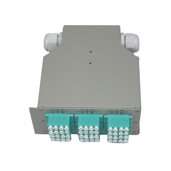
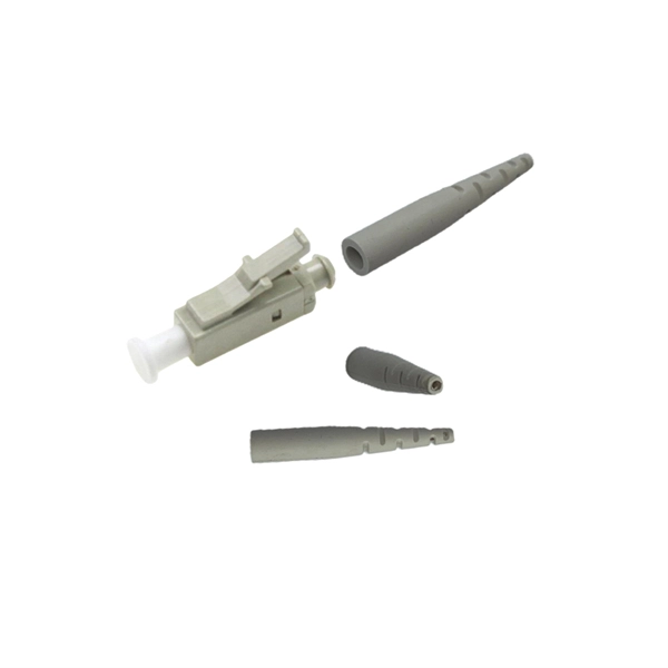
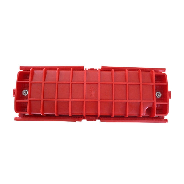
Optical fiber cold splice technology is based on the use of mechanical connectors to join two fiber-optic cables. These connectors are designed to align and join the fibers together in a precise and secure manner. This guide covers everything: what fiber optic pigtails are, how they differ from patch cords, which connector and polish type to specify, how to choose between mechanical and fusion splicing, and the real-world applications where pigtails are the right call. The connectors used in cold. Most fibers can be mechanically stripped without the aid of chemicals or heat. The recommended cleaning solvent for connectors and tools is isopropyl alcohol (reagent grade, 99% or beter). Do not use acetone for cleaning. They directly affect insertion loss, return loss, reliability, and long-term network stability. In this guide, we break down the most common optical fiber. In this beginner-friendly guide, we'll explain what it is, why the “APC” matters, the different types you can buy, how to select the right model, and how to install and test it correctly. What is an SC/APC Fiber Optic Adapter? An SC/APC fiber optic adapter is a passive mechanical interface used to. FASTConnect® field-installable connectors are factory pre-polished connectors that completely eliminate the need for hand polishing in the field. Proven mechanical splice technology ensuring precision fiber alignment, a factory pre-cleaved fiber stub and a proprietary index-matching gel combine to.
[PDF]
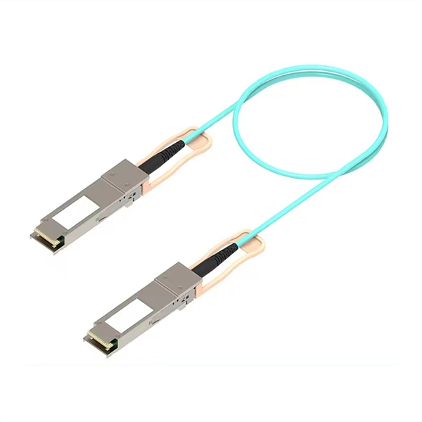
Most systems operate by transmitting in one direction on one fiber and in the reverse direction on another fiber for full duplex operation. Most systems use a "transceiver" which includes both transmission and receiver in a single module. The optical module serves as a crucial component in optical fiber communication systems, operating at the physical layer, which is the lowest layer in the OSI model. Its primary function is to achieve optoelectronic conversion by converting electrical signals into optical signals and vice versa. Operating at the physical layer of the OSI model, optical modules are core devices in optical. An optical module is a typically hot-pluggable optical transceiver used in high-bandwidth data communications applications. Optical modules typically have an electrical interface on the side that connects to the inside of the system and an optical interface on the side that connects to the outside. In the world of fiber optic communications, optical transceiver modules play a pivotal role as interfaces that convert electrical signals to optical signals and vice versa.
[PDF]