This guide shows you how to organize circuit breaker wiring properly. You will learn to build a safe, efficient, and professional electrical system today. Circuit breaker wiring configurations involve organizing main switches, busbars, and branch breakers within a distribution box. An electrical panel box, also known as a breaker box or a distribution board, is a crucial component of any electrical system. It serves as a central hub for distributing electricity throughout a building, ensuring that power is delivered safely and efficiently to all the required locations. Learn how to wire a distribution box step by step! This video shows real on-site footage of electrical installation, demonstrating safe and standardized wiring methods used by professionals. Wiring Direction: Wiring between the main circuit breaker and each branch circuit breaker in the box generally. Hey, in this article we are going to see the Single Phase Distribution Box Wiring Diagram and Connection Procedure. And all the switching and protective devices are installed in the. Messy distribution boxes are dangerous and very hard to fix. It receives power from the main electrical supply and divides it into separate circuits, each.
[PDF]
A single gang (or 1-gang) box is only wide enough for 1 switch or outlet. And so on all the way up to 10 gangs. Electrical box dimensions typically refer to: Correct dimensions ensure: Single-gang boxes are the most common type, used for one switch or outlet. Common uses: wall outlets, light switches, low-voltage controls. Tip: Depth is. They come in various sizes to accommodate different wiring needs and device configurations. Typically, PVC switch boxes are available in the following standard sizes: **Single gang box**: Usually around 2 x 3 inches, ideal for controlling a single switch or outlet. This guide helps you determine the correct dimensions based on wire fill capacity, device requirements, and installation environment, ensuring a safe and efficient electrical system. Some of the best distribution types are: 1. Main Distribution Board (MDB) The MDB act as a central section to distribute electricity to various sections with a residential or industrial units. Used in industrial automation and process control. Houses PLCs, relays, contactors, and wiring. Supports control. Article Summary: Calculating the correct junction box size per the NEC 2023 involves a process known as a “box fill calculation,” primarily governed by NEC Article 314. The first step is to determine the total number of conductor equivalents in the box. This count includes each conductor.
[PDF]
A new partnership between INNOVO, Castrol ON, and LiquidStack aims to bring the UAE its first modular, AI-ready liquid-cooled data centre. Imagine a data center where even the most powerful switches run cool and stable— without noise, thermal throttling, or energy waste. Cisco is actively innovating in direct-to-chip liquid cooling for high-performance switches, laying the groundwork for solutions that will enable seamless and. Read about the UAE's artificial intelligence advancements and other news from the UAE Embassy in DC. INNOVO, Castrol ON, and LiquidStack collaborate on a proof-of-concept unit aimed at meeting rising AI and high-performance computing demands in the GCC. The company is reportedly developing an ORv3W-based data center server rack. Hewlett Packard Enterprise announced a new managed data centre hosting service in the UAE in partnership with Khazna Data Centres (Khazna). The new service supports the UAE's.
[PDF]
Fiber optic cables are, like their name suggests, a cable that uses light, rather than electricity to transmit information. They're made from silica glass fibers about the same width as a human hair, which all.
[PDF]
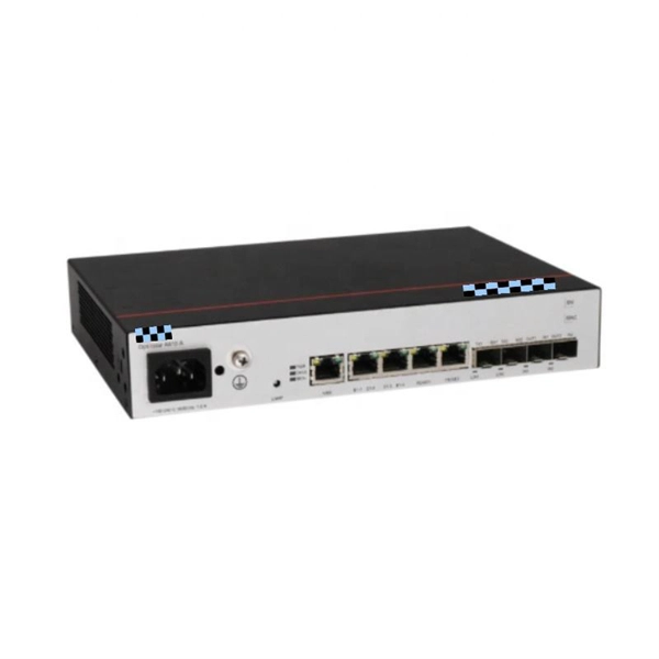
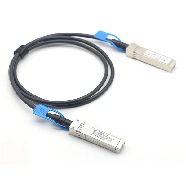
They support devices like IP cameras, wireless access points, and IoT devices, enabling placement in remote areas without nearby power outlets, a capability that regular switches lack as they can only handle data transmission and require a separate PoE injector for power supply. Network switches form the backbone of any Local Area Network, or "LAN" (pronounced "lan") for short. On this page you will learn what differentiates a PoE enabled switch from a regular LAN switch, when you should use a PoE switch versus a PoE injector and, what exactly is PoE (Power over Ethernet). A PoE (Power over Ethernet) switch is a network switch that delivers both power and data through a single Ethernet cable to connected devices such as IP cameras, VoIP phones, wireless access points, and IoT devices. This eliminates the need for separate power adapters, reducing cable clutter and. In today's blog, we'll explain what a PoE switch is and how it powers devices through one Ethernet cable. We'll also look at the different types of PoE switches, their benefits, and how they can be used in real-world situations. What Is PoE (Power. PoE switches deliver power and data over Ethernet cables, eliminating the need for separate adapters. For businesses, this simplifies deployment of IP cameras, access points, and VoIP.
[PDF]
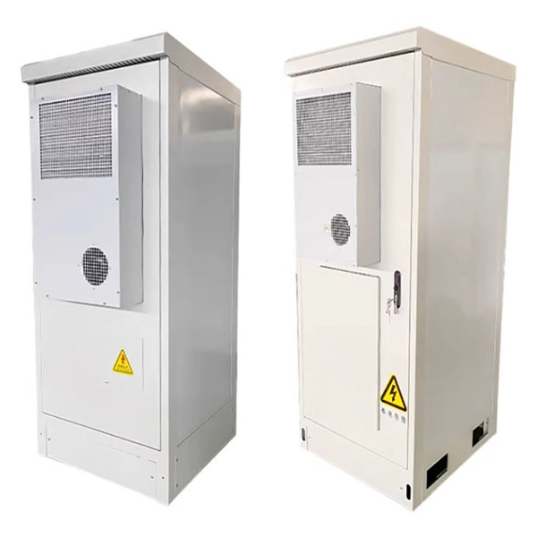
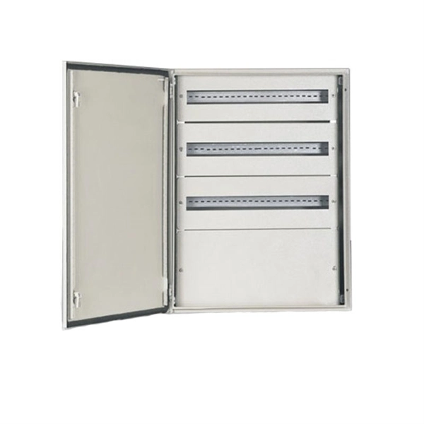
To choose a home distribution box, you must count your circuits and add 30% spare space. Then, select a main switch that handles your total load. Finally, choose safety devices like RCBOs and Surge Protection Devices (SPD) for the best protection against faults and lightning. A distribution box, sometimes referred to as a panel board, distribution board, or breaker panel, is an essential part of electrical systems that makes it easier to distribute electricity throughout a structure. It receives power from the main electrical supply and divides it into separate circuits, each. For procurement professionals, electrical contractors, and project managers, choosing the right Distribution Box (DB Box) is a critical decision that directly impacts system safety, reliability, and long-term operating costs. This ultimate guide explains what a distribution box does, its internal. What size distribution box do you need for a house? How do you know which circuit breaker to use? Can you add more breakers later? Why do you need GFCI or AFCI breakers? Choosing the right size and setup for your distribution box keeps your electrical system safe and working well. Let us look at the. As the main switch is separated from the whole distribution box, it can also be used as the power supply terminal (including bus bar) for the protection function of switching, and can also be used as the backup protection circuit of feeder. The power cabinet is a combination of electrical control.
[PDF]
The generally accepted and code-compliant height for switches is typically 48 inches (4 feet) from the finished floor to the top of the switch box. This standard helps ensure accessibility and consistency across installations. While the National Electrical Code (NEC) doesn't specify a mandatory standard outlet height for most general-use receptacles, established industry best practices and accessibility laws provide clear guidance. The NEC (Article 210. 52) specifies where receptacles must be placed (spacing along walls, required. The commercial electrical code requires switches at 42 to 48 inches and receptacles at 18 inches above finished floor in most applications. This height is an ergonomic choice, aligning well with the average reach.
[PDF]
The layer 2 switches collect the data from core switches, identify the type of data packet and the address of the access device. Selective routing and switching take place at the distribution layer. Those new distribution switches will have L3 redundant connections to the CORE switches running EIGRP so this will provide us high availability and load balacing. The connection between these distribution switches is going to be a L3 link (Cisco recommendation) in order to summarize our networks to. · Layer Positioning: The data link layer (Layer 2) of the OSI model, realizing local forwarding of data frames based on MAC addresses. · Core Task: Establishing direct interconnections between devices within a local area network to ensure efficient communication within the same network segment. ·. Layer 2 Switch is a form of Ethernet switch that switches packets by looking at their physical addresses (MAC addresses). These switches operate at the data-link layer (or layer 2) of the Open Systems Interconnection (OSI) reference model. At Layer 2, edge switches use media access control (MAC) addresses to manage traffic within a local area. The core layer is the backbone of the network. The distribution layer connects the access layer to the core layer. When designing a campus LAN, you may. Physical Layer - Physical layer of TCP/IP model is responsible for physical connectivity of two devices. It contains multiple input/output ports.
[PDF]
Calculate the optimal number of access points and bandwidth requirements for your space. Get professional recommendations based on IEEE 802. 11 standards and industry best practices. Fill out the form to get your Wi-Fi capacity recommendations. Understanding how to calculate the number of access points needed is crucial for designing efficient wireless networks that provide optimal coverage and connectivity. This guide explores the key concepts, formulas, and practical examples to help you plan your network effectively. An access point is. Wireless Access Points Calculator: How Many Wireless Access Points Do I Need? Calculate the number of wireless access points needed for your space based on coverage area, user density, and environmental factors. Max associations per radio as stated earlier calculated at 60 users per radio for. One of the most common questions in Wi-Fi design sounds deceptively simple: How Many Access Points Do You Need? People usually expect a fast, fixed number as an answer. One access point for a small apartment, two for a villa, maybe five for an office. In reality, Wi-Fi does not work like that. It can be used to design a Wi-Fi network and get a sense of how many access points are required. 3 How are the numbers calculated? Enter The Wi-Fi AP range (explained below) of 33 feet is.
[PDF]
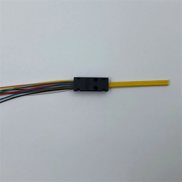
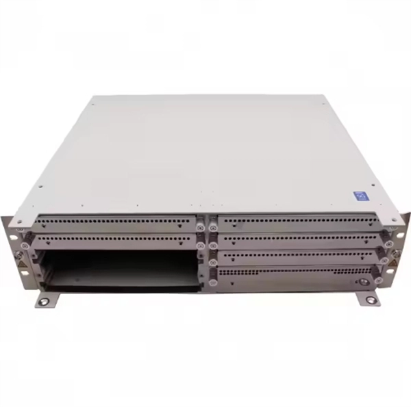
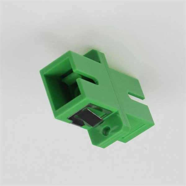
Control signal choices for fiber optic switches include RJ-45, RS232, RS422, and TTL. Common switch features include rack mountable and LED indicators. An important environmental parameter to consider for fiber optic switches i. Control signal choices for fiber optic switches include RJ-45, RS232, RS422, and TTL. Common switch features include rack mountable and LED indicators. An important environmental parameter to consider for fiber optic switches is the operating temperature. Fiber optic switches can interface with two types of cables: 1. single mode 2. multimode Single modeis an optical fiber that will allow only one mode to propagate. The fiber has a very small core diameter of approximately 8 µm. It permits signal transmission at extremely high bandwidth and allows very long transmission distances. Multimodedescribes. Important switch performance parameters to consider when searching for fiber optic switches include: 1. wavelength range 2. number of input ports 3. number of output ports 4. switching time 5. insertion loss 6. polarization dependent loss 7. cross-talk 8. data rate 9. switching voltage The wavelength range specifies the wavelength range the switch.
[PDF]
Variety of applications and services depend on data centers to provide the high reliability and availability of computing and storage resource at minimal costs. Along with the emerging of traffic boosting applic.
[PDF]
Various optically switched architecture prototypes, based on the above optical switches, have been proposed to demonstrate the potential of optical data center networks. Optical data center networks are mainl.
[PDF]
In this step-by-step tutorial, we'll cover: ✅ Tools you need ✅ Safety precautions ✅ Mounting the box ✅ Wiring tips ✅ Final checks Perfect for beginners, DIYers, and electricians who want a clear installation guide. more Learn how to properly install an electrical. Electrical switch box wiring is a critical aspect of any electrical installation. The electrical panel box wiring diagram provides a visual representation of. A junction box provides a code-approved place to house wire connections, whether for outlets, switches, or splices. Here's how to install one. We may be compensated if you purchase through links on our website. It acts as a central connection point for various electrical wires, allowing for the easy distribution of electricity to different fixtures and devices. A properly installed and wired junction box ensures the safety and. Are you ready to master the skill of building electrical panels? This detailed guide provides an excellent base for beginners. Learn about the essential components of panels, such as the circuit breakers and fuses that safeguard against hazards. Then, delve into complex wiring configurations.
[PDF]
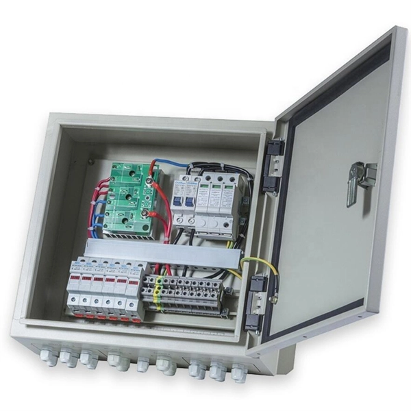
Take the appropriate rating of MCB and RCCB as per your load requirements. Identify the Input and Output sides of the MCBs and RCCBs. Connect the output of the Main MCB to the input. Primary distribution systems consist of feeders that deliver power from distribution substations to distribution transformers. A feeder usually begins with a feeder breaker at the distribution substation. Many feeders leave substation in a concrete ducts and are routed to a nearby pole. At this. Connection method: Each switch takes a wire from the incoming point and connects it to the incoming end of the switch, or uses parallel connection to reduce the difficulty of wiring. Wiring Direction: Wiring between the main circuit breaker and each branch circuit breaker in the box generally. Correct wiring methods for circuit breakers within distribution boxes are fundamental to ensuring electrical safety and compliance with established codes. The distinction between 1P and 2P circuit breakers plays a pivotal role in determining the appropriate protection level for various circuits. A primary distribution substation is the connection point of a distribution system to a trans-mission or a sub-transmission network. This guide shows you how to organize circuit breaker wiring properly. You will learn to build a safe, efficient, and professional electrical system today. Circuit breaker wiring configurations involve organizing main switches, busbars.
[PDF]
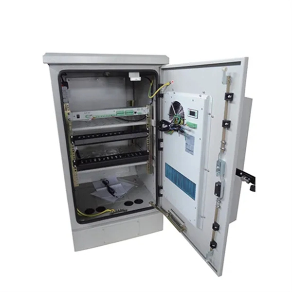
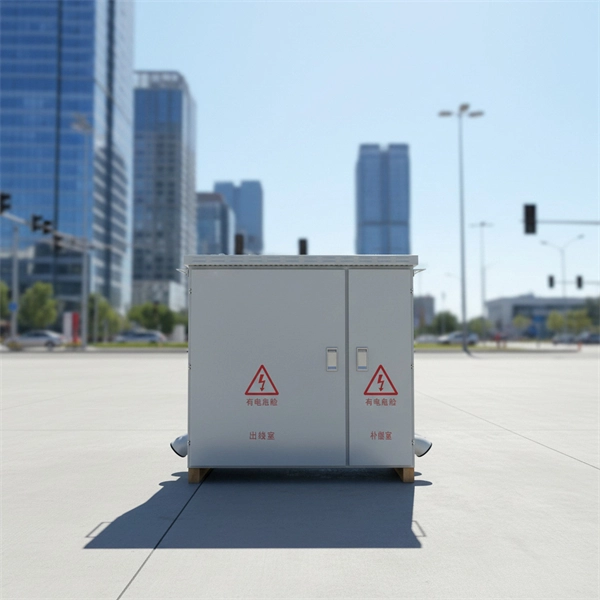
This video shows real on-site footage of electrical installation, demonstrating safe and standardized wiring methods used by professionals. Description: The BSL is illustrated in a low-voltage distribution panel wiring diagram. It consists of three main components: the voltage measuring circuit, secondary circuit protection, and the energy metering circuit. (1) The voltage measurement circuit uses a voltage conversion switch SA and. Primary distribution systems consist of feeders that deliver power from distribution substations to distribution transformers. A feeder usually begins with a feeder breaker at the distribution substation. Many feeders leave substation in a concrete ducts and are routed to a nearby pole. At this. Explosion-proof distribution boxes, vital terminal distribution equipment in power systems, play a crucial role in controlling and protecting industrial electricity in hazardous environments. Given their ubiquity, let's delve into the installation and wiring of indoor distribution boxes today. more Learn how to wire a distribution box step by step! This video shows real on-site footage of. Connection method: Each switch takes a wire from the incoming point and connects it to the incoming end of the switch, or uses parallel connection to reduce the difficulty of wiring. Wiring Direction: Wiring between the main circuit breaker and each branch circuit breaker in the box generally.
[PDF]