The laser diode market in Kazakhstan is experiencing growth, driven by expanding applications in sectors such as telecommunications, healthcare, and consumer electronics. Laser diodes find use in devices such as optical transmitters, barcode scanners, and laser pointers. Technological advancements. Blue Laser Diodes Market size was valued at USD 245 million in 2024 to USD 370 million by 2032, exhibiting a CAGR of 6. 2% during the forecast period. 7 billion in 2024 and is anticipated to grow at a CAGR of 14. 4% between 2025 to 2034. Rapid proliferation of high-power laser diodes in autonomous vehicle technologies. 744 USD Billion in 2024. The market drivers for the Blue Laser Diodes Market can be influenced by various factors. These may include: Growing Demand in Consumer.
[PDF]
The third part represents the number of spots in the beam splitter. The naming principle of the beam splitter is easy to illustrate with the following example. The models listed in the following table are examples After years of exploration, we can maintain all process parameters of the beam splitter stable and. A beam splitter or beamsplitter is an optical device that splits a beam of light into a transmitted and a reflected beam. It is a crucial part of many optical experimental and measurement systems, such as interferometers, also finding widespread application in fibre optic telecommunications. a laser beam) into two (or sometimes more) beams, which may or may not have the same optical power (radiant flux). Newport offers a wide variety of Beamsplitters in various shapes. Circular beamsplitters, plate beamsplitters and cube beamsplitters can be purchased for polarizing or non polarizing beamsplitting. Thorlabs offers a wide range of optical beamsplitters. Our plate beamsplitters have a coated front surface that determines the beam splitting ratio while the back surface is wedged and AR coated in order to minimize ghosting and interference effects. Additionally, beamsplitters can be used in reverse to combine two different beams into a single one. Beamsplitters are often classified according to their construction: cube or plate.
[PDF]
Multijunction vertical-cavity surface-emitting lasers (VCSELs) have gained popularity in automotive LiDARs, yet achieving a divergence of less than 16° (D86) is difficult for conventional extended cavity.
[PDF]
A T-tap wire connector, also known as a T-splice connector, is used to tap into existing wires and is characterized by its T-shaped design with three points of entry for wires. This allows you to install the connector on a wire and tap into it from the third entry point. The wall-mounted bracket features an integrated coupler for quick and easy installation, enhancing overall work efficiency. Corrosion-resistant galvanized coating protects against bad weather, moisture, and rust - ensures a long service life even in harsh environments. T-shape design provides both. How can we improve? Choose from our selection of T-connectors, including stainless steel pipe and pipe fittings, brass and bronze pipe and pipe fittings, and more. Same and Next Day Delivery. The NavePoint 00406777 electro zinc plated wire mesh cable tray t-shaped wall bracket is an ideal solution for neatly routing and organizing cables. Fast Docking Coupler Bar for Wire Mesh. Toolless Adapter Fitting for Fiber. The L-com LC-CRP100 T-shaped wall bracket offers a perfect way for mounting and securing the wire mesh cable tray to the wall. Made by Quest Manufacturing, this add on accessory is durable and reliable, and will hold the wire mesh safely, so you can place cables & wires in. Design Shape This bracket is designed with a T shape which provides support.
[PDF]
In this video, we'll walk you through the process of wiring a home distribution box with a detailed connection diagram. Whether you're an electrician or a DIY enthusiast, this guide will help you understand the basics of home electrical distribution. more Welcome to our. An electrical panel box, also known as a breaker box or a distribution board, is a crucial component of any electrical system. It serves as a central hub for distributing electricity throughout a building, ensuring that power is delivered safely and efficiently to all the required locations. Follow this guide for a clear and safe connection process: Before starting, always ensure the main power is turned off to avoid electrical shock. Covers wiring, placement, standards, and expert tips for a compliant setup. It takes the incoming power and safely distributes it to different circuits throughout your building. This panel routes power from the utility service to every circuit while housing circuit breakers that provide overcurrent protection. What is Distribution Board? Distribution board.
[PDF]

The cable identifier: An alphanumeric code that differentiates this cable from other cables within your facility. Make sure you use a consistent format, such as "FB-03-A142" where FB indicates fiber, 03 is either the zone or floor while A142 represents the exact cable number. The text on the cable starts with the Corning product name "Corning Rocket Ribbon (TM) Optical Cable," date of manufacture "01/2022" and a serial number. Here is the most important information: 864F means the cable contains 864 fibersSM. It was a short length of Corning Rocket Ribbon 864 fiber cable left over from an installation by a contractor. While walking down the street near the Fiber Optic Association's office recently, we found a scrap of fiber optic cable laying in the gutter. What a find! It was a short length of Corning. The WebTrak serial number can be found on the label located on the back side of the antenna. For BSAs you will need the year of manufacture, plant prefix and serial number. You will need to combine this information to create the WebTrak number needed to search for the report on the website. The. The printings on the fiber optic cable jacket are the markings on the cable's outer layer that provide essential information about its specifications and applications. This notation indicates that you are looking at either OM2, OM3, or OM4, as they all have this core and cladding measurement.
[PDF]
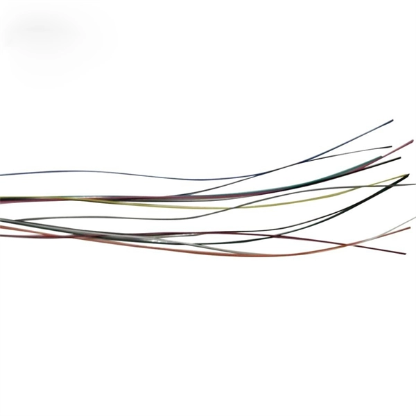
Single-mode fiber optic cable typically has a single core. This means that it consists of a single strand of glass fiber that carries light signals. The core is the central part of the cable through which the light travels, surrounded by a cladding layer that helps guide the light. One key factor is the number of cores, which impacts how much data you can transmit. This post will guide you through understanding fiber optic cores and selecting the perfect cable for your needs. Single-mode: A. The number of optical cores in an optical fiber is the total number of equipment interfaces multiplied by 2, plus 10% to 20% of the spare quantity, and if the communication mode of the equipment has serial communication and equipment multiplexing, you can reduce the number of cores. The number of. Common fiber cores include 1 core, 2 cores, 6 cores, 8 cores, etc., and there are many types. The total number of cores for a 1pc fiber patch cable is calculated as the number of. The most common type of fiber optic cable used in telecommunications is single-mode fiber, which usually has a single core.
[PDF]
Professional home circuit calculator per NEC Article 210 and 220. Determines the total number of branch circuits, wire sizes, breaker ratings, and GFCI/AFCI protection requirements for residential electrical systems. Covers general-purpose lighting circuits, small appliance circuits, laundry. Before determining the required number of circuits and associated calculations, let's define and differentiate between branch circuits, general-purpose lighting branch circuits, and individual branch circuits. According to NEC Article 100 – Definitions: Branch Circuit: Refers to the conductors. Before we dive into calculations, let's get familiar with a few essentials: 1. Your Project's Total Power Demand This isn't just adding up wattages randomly. Think of your home as a busy kitchen—not every appliance runs at once. Do you really need the hair dryer, microwave, and vacuum running. Professional electrical panel schedule tool for creating detailed load distributions, calculating circuit loads, balancing phases, and ensuring NEC compliance for electrical distribution panels. Panel schedules are essential for electrical system documentation, load analysis, and NEC compliance. Compute the branch circuits, feeders, service-entrance conductors, and wire protection. How do you determine the minimum number of general lighting and general-use branch circuits required by the NEC for dwellings? A.
[PDF]
This study aims to develop a simple yet efficient performance-based design optimization methodology for cable tray systems in building structures. In the paper, the drift ratio between adjacent supports i.
[PDF]
Enter the dimensions of the cable tray, the desired fill ratio, and the diameter of the cables to calculate the cable tray capacity. This calculator helps determine the maximum number of cables that can be laid in a cable tray while adhering to the specified fill ratio. The following formula is. Calculate cable tray sizing and fill capacity based on tray dimensions, cable diameter, number of cables, and maximum fill percentage per electrical code. Determine whether cables fit within safe fill limits. Cable tray fill capacity is governed by electrical codes (typically NEC Article 392) which. Our cable tray fill calculator is designers to compute the appropriate size and capacity of cable trays. 5 inches, in a 4-inch deep cable tray. The calculator would help determine if the chosen tray is sufficient or if a larger size is. A Cable Tray Capacity Calculator is an essential tool for electrical engineers, contractors, and project managers involved in the installation and management of electrical cables. NEC code limits tray fill to 40– 50% depending on tray type, leaving room for airflow, future cables, and bend radius. Calculate the total cable cross-section area and divide by tray area. Follow these simple steps: Define Tray Dimensions: Enter the width and depth of your planned cable tray (in mm or inches). Select Fill Standard: Choose 40% for power cables (NEC compliant) or 50% for.
[PDF]
You simply multiply the number of splices by the estimated loss per splice. It's that easy! ✨ Let's say you have a long fiber run that requires 4 fusion splices to connect different cable segments. 4 dB is the total attenuation you'll add to your loss budget just for the. Fusion splicing is the process of fusing or welding two fibers together usually by an electric arc. Fusion splicing is the most widely used method of splicing as it provides for the lowest loss and least reflectance, as well as providing the strongest and most reliable joint between two fibers. There are several ways to know the number of multi-spliced cores. For example, 12 core fibers, 12*2=24 cores, 12 cores at the beginning and 12 cores at the end; 2. Count the number of optical fiber. Calculating the total loss from splices in a cable run is wonderfully straightforward. Connectors: Total number of connectors in design. Laser: A device which produces a single frequency light. The guide provides the complete workflow, covering safety precautions, tool selection, fiber preparation, fusion operation, quality control, and. Recommendation ITU-T L. 12 specifies splices of single-mode and multimode optical fibres. It describes suitable procedures for splicing that should be carefully followed in order to obtain reliable splices between single optical fibres or ribbons.
[PDF]