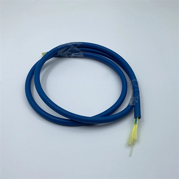
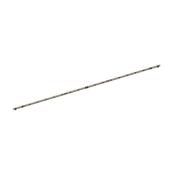
Designed specifically for deployment alongside power lines and utility poles, ADSS eliminates the need for metallic components and external support structures, making it a go-to choice for power grid communications, smart cities, and rural connectivity. AFL-ADSS® (All-Dielectric Self-Supporting) fiber optic cable is a non-metallic cable which supports its own weight without the use of lashing wires or messenger cables., Ltd as a 20 Years Reliable ADSS cable Manufacturer, We can supply 2-288 Cores single sheath ADSS fiber cables for span range from 200m to 1500m, We can customize the number of cores of ADSS cables according to the needs of our customers. It is used by electrical utility companies as a communications medium, installed along existing overhead transmission. We are a manufacturer of (ADSS)dual double jacket sheath aramid yarn All Dielectric Self-Supporting Optical Fiber Cable 2-288 core Manufacturer. We supply fiber optic Cable in competitive cost and short lead time. Both single mode and multimode fibers can be arranged in ADSS cables with a maximum of 144 fibers. ADSS fiber optic cable is designed for outside plant. The All-dielectric Self Supporting (ADSS) Cable has emerged as a cornerstone of modern aerial fiber optic deployments, offering unmatched durability, flexibility, and performance in challenging environments. Designed for seamless integration into power line infrastructures, telecom networks, and.
[PDF]
The core switch functions as the central point of the entire network, forming the high-speed backbone for the organization's data infrastructure. Its primary purpose is to provide an optimized and reliable transmission structure for all aggregated data traffic. Simply put, it's the kingpin that keeps your network humming. You may also want to know: Can a Nintendo Switch Play DS Games? ·. A network switch connects multiple devices within a local area network (LAN) and directs data packets only to their intended destination. In large organizations, networks become complex, exchanging massive amounts of data. The core switch is the most important piece of hardware in this. A core switch is a high-capacity, high-performance Layer 3 switch positioned at the physical backbone of an enterprise network. Engineered to aggregate massive volumes of data from distribution switches, it provides ultra-low latency and maximum throughput to ensure uninterrupted routing and packet. A core switch is a crucial component of a network infrastructure that serves as the backbone of a network. It's a high-performance switch that provides high-speed connectivity between different network segments, which may include access switches, distribution switches, and routers. These switches are high-capacity, usually handling the greatest amount of traffic compared to other switches in the network. They primarily focus on speed.
[PDF]
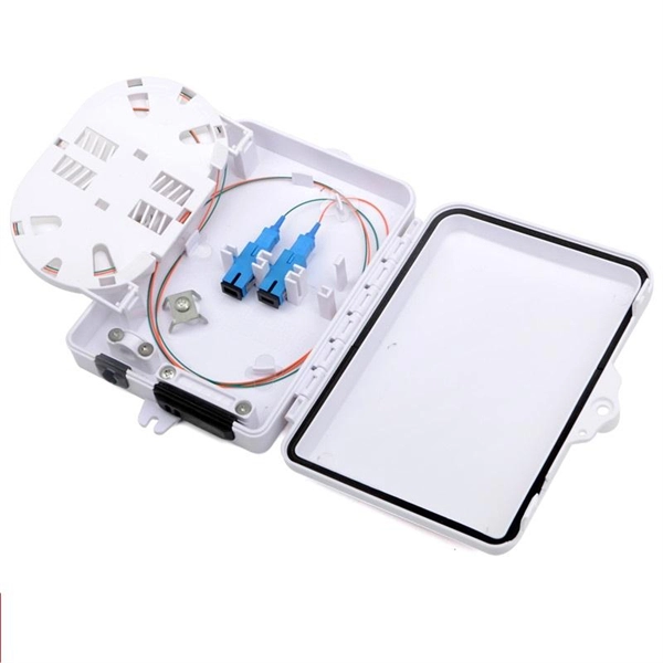
The drop cable connects your home, the patch panel organizes the network, the splice keeps connections seamless, and the optical splitter shares the signal with your neighbors. The fiber drop cable is what makes a true fiber-to-the-home (FTTH) connection possible. It's the final link in the chain that ensures you're getting the full, unfiltered power of fiber internet, not a mix of fiber and older technology. From the street to your living room, every piece of the fiber. To begin, the standard definition of splicing in optical fiber is joining two fiber optic cables together. The other, more common, method of joining fibers is called termination or connectorization. Splicing is most commonly used in the field but has application in cable assembly houses. Infield. In many applications of fiber optics, it is necessary to connect fiber ends (terminations) in some way such that light from one fiber can get into the other fiber without losing too much of its optical power. This creates a permanent and low-loss connection. Both techniques have their advantages and are suited for different applications, but understanding which method to use can greatly impact the network's. Many installations involve splitting the fibers in a cable or dropping a small fiber count cable from a large backbone cable. Backbone cables of 144-288 fibers are common and larger ones are becoming more common too. Drop cables are often only 2-12 fibers, meaning most fibers are continuing.
[PDF]
Dual fiber modules use two fibers. They are easier to set up and give steady communication. They use a thin fiber core. They cost less and are. IntroductionEngineers, purchasing managers and installers often see the terms Transceiver, optical module and fiber optic module used interchangeably — and that causes confusion. This article answers the question directly and precisely: what each term usually means, where they overlap, and what. Optical modules and fiber optic transceivers are both essential components in fiber optic communication systems. Optical module: belongs to a. However, there are still many things that need to be paid attention to about how to link the optical fiber and the optical module. An optical module is a functional module, or an accessory. It is a passive device that cannot be used alone. It can only be used in switches and devices with optical.
[PDF]
652 single-mode fiber, G. 655 single-mode fiber has lower dispersion in C-band (1530nm~1565nm), so the function of the optical amplifier in this band can be maximized, and the core area of the fiber is larger. Compared with G. 652B single-mode fibers are not suitable for wavelength division multiplexing applications because of their water absorption characteristics. 655 fiber is designed to reduce the effects of chromatic dispersion and PMD compared to G. It has significantly lower dispersion characteristics, enabling longer transmission distances and higher data rates. Non-Zero Dispersion Shifted (NZDS): G. 655 fiber. G652 is currently the most popularly adopted single mode fiber, for which G652 is defined as Standard SMF. It has G652A, B, C and D four versions. G652A and B have a zero dispersion wavelength point at 1310 nm, which makes it a natural fit for operation in the 1310 nm band. However, they are not. Among them, G. D fibers possess higher performance than G. The more recent variants, G. D, feature a reduced water peak that allows them to be used in the wavelength region between 1310.
[PDF]
Instead of fusing one fiber at a time, mass fusion splicing can fuse up to all 12 fibers in one ribbon at once. Many of today's cables with high fiber count involve subunits of 12 fibers each that can be quickly ribbonized. Fiber optic joints or terminations are made two ways: 1) splices which create a permanent joint between the two fibers or 2) connectors that mate two fibers to create a temporary joint and/or connect the fiber to a piece of network gear. Either joining method must have three primary characteristics. Fiber optic splicing is the process of seamlessly joining two single Splicing has a lower optical loss and back-reflection than other terminations, making it the ideal choice for maintaining signal integrity and reliability in fiber optic networks. There are numerous use cases for fiber optic splicing. Through splicing, fiber optic technicians can extend the length of the fiber to make it long enough for use in a required cable run. As. To begin, the standard definition of splicing in optical fiber is joining two fiber optic cables together. The other, more common, method of joining fibers is called termination or connectorization. Splicing is most commonly used in the field but has application in cable assembly houses.
[PDF]
Factory terminated pigtails can easily be fusion or mechanically spliced to an existing fiber line. Custom lengths, connector combinations and. This 12-fiber optic pigtail is designed for efficient fusion splicing in structured cabling systems. It supports data centers, CATV, PON, WDM/DWDM multiplexing, FTTH, and voice services in ATM and SONET networks. With OS2 bend-insensitive fiber, it minimizes attenuation caused by bends or twists. ( Order Today, Ship before 05/01/2026 ) We supply LC/APC Single mode 12 Pack Multi Color Fiber Optic Pigtails with competitive price. We supply quality LC/APC Single mode Fiber Optic Pigtails are 12 packs that are 3 meters long with 900um outter jacket. Ideal for fusion splicing. We also offer. New to ADI? Become a Customer Please sign in to view pricing, availability, and to add to cart. Country of Origin: United States. Featuring LC style connectors, these pigtails are sold in a convenient 12 pack. FS 12 fibers pigtails with LC SC connectors feature color-coded or bunch design for various fiber splicing applications. 100% end-face, 3D interferometer, IL & RL tested. The LC APC 12 core bundle fiber optic pigtail consists of twelve individual fiber optic pigtails, each terminated with an LC APC connector on one end.
[PDF]
The layer 2 switches collect the data from core switches, identify the type of data packet and the address of the access device. Selective routing and switching take place at the distribution layer. Those new distribution switches will have L3 redundant connections to the CORE switches running EIGRP so this will provide us high availability and load balacing. The connection between these distribution switches is going to be a L3 link (Cisco recommendation) in order to summarize our networks to. · Layer Positioning: The data link layer (Layer 2) of the OSI model, realizing local forwarding of data frames based on MAC addresses. · Core Task: Establishing direct interconnections between devices within a local area network to ensure efficient communication within the same network segment. ·. Layer 2 Switch is a form of Ethernet switch that switches packets by looking at their physical addresses (MAC addresses). These switches operate at the data-link layer (or layer 2) of the Open Systems Interconnection (OSI) reference model. At Layer 2, edge switches use media access control (MAC) addresses to manage traffic within a local area. The core layer is the backbone of the network. The distribution layer connects the access layer to the core layer. When designing a campus LAN, you may. Physical Layer - Physical layer of TCP/IP model is responsible for physical connectivity of two devices. It contains multiple input/output ports.
[PDF]
A fusion splicer is a specialized device used to join two optical fibers end-to-end through the process of fusion. By aligning the fibers precisely and applying a controlled electric arc, the fusion splicer melts the ends of the fibers, creating a single, continuous fiber. Fusion splicers are essential for creating low-loss, high-performance fiber optic connections in telecom, FTTH, and data center applications. The best splicers offer core alignment, fast splice times, durable designs, and smart features like cloud syncing and automated calibration. This process minimizes. Fiber splicing is the process of permanently joining two fibers together. Unlike fiber connectors, which are designed for easy reconfiguration on cross-connect or patch panels. There are two types of fiber splicing – mechanical splicing and fusion splicing. It is the technique that has the least insertion loss and almost no back reflection, hence ensuring strong connections over a long period. Fiber optic splicers are.
[PDF]
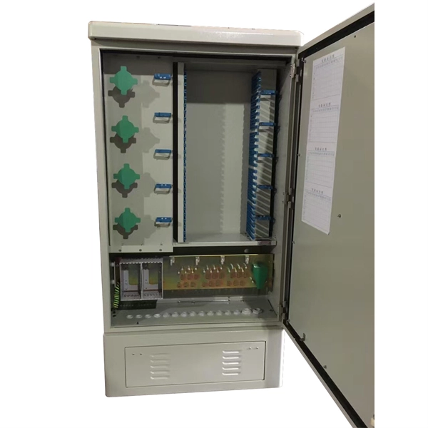
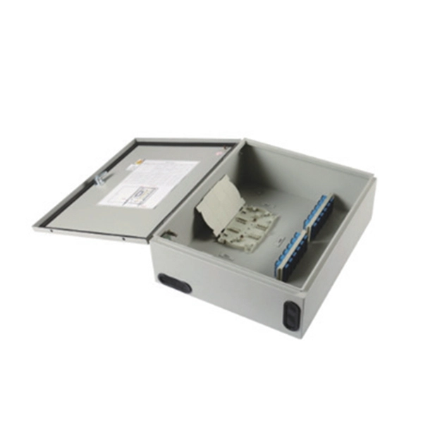
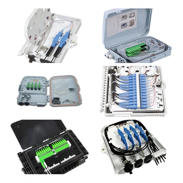
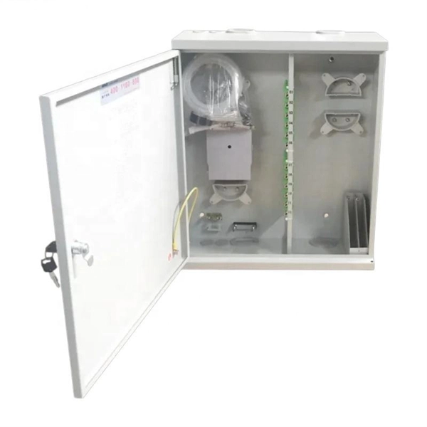
After an optical cable arrives at the user's end, it is fixed in the terminal box. Then, the optical cable core and pigtail are welded in the terminal box. These boxes are similar to MDF in telephone exchange.
[PDF]
The number of core switch ports is large, usually modular, and can be freely matched with optical ports and Gigabit Ethernet ports. The general core switches are Layer 3 switches, and various advanced network protocols such as routing protocol/ACL/QoS/load balancing can. Does every network need a core switch? Can a router be used instead of a core switch? How do I determine the bandwidth requirements for my core switch? What security features should I look for in a core switch? How often should I update the firmware on my core switch? What are the key performance. Home / Ethernet Switch / Do I need a core switch? The simple answer is “yes. ” Every complex network comprises multiple computers and devices. To route the traffic and improve the performance of the network, you must have a proper mechanism. What would you employ to simplify the network? The core. ● Up to 28 native nonblocking 40/100 Gigabit Ethernet QSFP28 ports. 3-GHz x86 CPU with 8 cores and 32 GB of DDR4 memory. ● Up to 960 GB of SSD. rity to ensure guests and property peaceful and safe. Our solutions provide stable and continu arge commercial buildings host many separate entities. The primary function is to access user data or aggregate some switch data at the access layer. This kind of switch can configure Vlan simple routing protocol and some simple. The number of conventional switch ports is generally 24-48.
[PDF]
A core switch is a crucial component of a network infrastructure that serves as the backbone of a network. It's a high-performance switch that provides high-speed connectivity between different network segments, which may include access switches, distribution switches, and routers. Engineered to aggregate massive volumes of data from distribution switches, it provides ultra-low latency and maximum throughput to ensure uninterrupted routing and packet. It's more than just a switch; it's the central nervous system of your network infrastructure. Its primary function is to rapidly forward data packets between. Professional networks are structured using a three-tier hierarchical model to ensure scalability and efficient traffic management. This model divides the network into three functional layers: the Access Layer, the Distribution Layer, and the Core Layer. The Access Layer sits at the edge, using. Core switches are the focal point for traffic control between access and distribution switches. They perform a vital function in ensuring the network's reliability and stability because they are in charge of routing data across the network infrastructure in a reliable and timely manner. They operate at the data link layer (Layer 2) or the network layer (Layer 3) of the OSI (Open Systems Interconnection) model, facilitating the communication of devices on a network by receiving, processing.
[PDF]
The generally accepted and code-compliant height for switches is typically 48 inches (4 feet) from the finished floor to the top of the switch box. This standard helps ensure accessibility and consistency across installations. While the National Electrical Code (NEC) doesn't specify a mandatory standard outlet height for most general-use receptacles, established industry best practices and accessibility laws provide clear guidance. The NEC (Article 210. 52) specifies where receptacles must be placed (spacing along walls, required. The commercial electrical code requires switches at 42 to 48 inches and receptacles at 18 inches above finished floor in most applications. This height is an ergonomic choice, aligning well with the average reach.
[PDF]
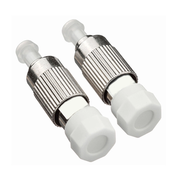
Singlemode G652D fiber optic pigtail is with low water peak fiber which provides expanded transmission window from 1310nm to 1550nm continuously for long distance transmission with features of low attenuation, high performance, long term reliability. FS fiber optic pigtails offer a fast way to make fiber optic communication devices in the field by fiber splicing, fully manufactured and tested by industrial standards. Explore our range of pigtails optimized for OS1 single-mode and OM1, OM2, OM3, OM4, and OM5 multimode fibers. The SM fiber are used in wavelength region. Fiber optic pigtail is a piece of fiber optic cable with only one fiber optic connector on one side of the cable, there are single mode and multimode fiber optic pigtails, which can be with various types of fiber optic terminations such as LC, SC, ST, FC, MTRJ, MU, E2000, MPO, etc. The typical use. FiberMania's Fiber Optic Pigtails are designed to deliver stable, high-performance connections for a wide range of fiber optic network applications. Available in single-mode and multimode options, our pigtails ensure low insertion loss, excellent return loss, and long-term reliability, making them. Optical fiber pigtails are recommended or sometimes required when there is a need to make a transition from thin buffered fibers (250-900 µm), typical for distribution cables and not suitable for direct optical fiber connector termination, to cross-connection or equipment connection points.
[PDF]
This is determined by the speed capability of one individual port on your switch. If each port supports 1 Gbps, then each port's capacity is simply that – 1 Gbps. To estimate the switch's overall capacity, multiply the per-port speed by the total number of ports on the switch. Well, understanding how to calculate the switching capacity of your switches is the first step! What is Switching Capacity? Let's start from square one. Switching capacity, often known as fabric capacity, is the total amount of data a switch can process and transfer in a given second. This. These examples help compare common edge switch scenarios. This calculator blends physical port bandwidth, demand estimation, and planning margin into one capacity model. The 20-byte packet overhead is a practical approximation for wire-rate planning. Enter the number of access ports that serve. Calculating a network switch's capacity, often referred to as its backplane bandwidth or switching fabric capacity, is crucial for determining if it can handle the anticipated network traffic without creating bottlenecks. Whether you're managing a small office network or a large enterprise setup, understanding switching capacity is essential for ensuring optimal performance. When the switch achieves line speed (maximum forwarding speed), the.
[PDF]