The first step to finding the right KVM switch is taking inventory of what you'll use it with: specifically, the number of computers, monitors, and additional peripherals, such as a keyboard and mouse. Yo.
[PDF]
Setting up a KVM switch for dual monitors with both a laptop and a desktop is a straightforward and empowering experience. Now that I've guided you through the entire setup process, it's time for you to dive in and try it yourself. A KVM switch (with KVM being an abbreviation for "keyboard, video, and mouse") is a hardware device that allows a user to control multiple computers from one or more sets of keyboards, video monitors, and mouse. Switches to connect multiple computers to one or more peripherals have had multiple. A KVM switch allows you to use one set of peripherals to control multiple computers, making it easier to switch between them without having to unplug and plug in cables. There are different types of KVM. Desktop KVM switches are compact devices that allow a user to access two, four, eight, or 16 computers from a single user console eliminating the need for extra peripherals, while providing faster access to critical applications. This can be particularly beneficial when there is insufficient room for multiple monitors and keyboards, such as in a server room. So what you need is an HDMI Switcher box, like the one I have here, the name is AV Access 4K HDMI KVM Switcher and just like the name says, it allows you to switch from one device to another by the push of a button. And not only that, if you're using multiple computers or devices that use mouse and.
[PDF]
For each laptop, PC, or game console in the setup, you shall connect both their video out and USB port to the KVM switch. For each system, the ports are grouped and numbered. Put each cable in the rig.
[PDF]
A KVM switch is built as a box in metal. For most designs, there are ports for the USB host, video inputs and outputs on the back panel, and a USB hub and switch buttons on the front panel. In simple terms, a KVM switch allows you to switch between different computer sources (or computer cases) while still using the same keyboard, monitor, and mouse; in fact, that's what KVM stands for: Keyboard, Video, Mouse. That means if you have several PCs you need to work with, you don't have to. KVM switch connects more than one PC with a single keyboard, monitor, and mouse. It enhances efficiency, saves your space, and brings down costs. This simple yet powerful device lets you control several computers using just one set of peripherals. In this article, we'll explore what is a KVM switch, its functionality, and its benefits for both work and gaming environments. We'll also provide tips on selecting the ideal KVM. A KVM switch (with KVM being an abbreviation for "keyboard, video, and mouse") is a hardware device that allows a user to control multiple computers from one or more sets of keyboards, video monitors, and mouse.
[PDF]
The IEEE standard for the base PoE switches is 802. 3at for PoE+, and 802. PoE and PoE+ transmit power over two pairs of twisted-pair wires in their cables, while the PoE++ variants use four pairs of twisted-pair wires. The splitter is the silver and black box in the middle between the wiring junction box (left) and the access point (right). The PoE connection eliminates the need for a nearby power outlet. In another common configuration, the access point or other connected device includes internal PoE splitting. Power over Ethernet (PoE) switches combine data and power delivery into a single Ethernet cable, simplifying deployment of devices such as access points, IP cameras, VoIP phones, and IoT equipment. PoE does not reduce network speed, does not waste excessive power when proper cabling standards are. Therefore, everyone is concerned about whether PoE switches will affect speed. Key Benefits of Power over. PoE switches (Type 1) comply with the IEEE 802. 3af standard, which specifies the maximum power delivered over Ethernet cables.
[PDF]
Quick Answer: To check CPU utilization on a Cisco switch, use the command “show processes cpu” in the CLI. This displays current CPU load, CPU usage history, and process-specific details, aiding in network performance troubleshooting. The CPU becomes too busy when either an IOS process consumes too much CPU time or the CPU receives too many packets from the switching hardware. When either of these two CPU consumers requires the CPU resource to the detriment of the other, then the CPU is too busy. For instance the CPU is. High CPU utilization on Cisco switches can lead to degraded network performance, packet loss, and even switch failures. Identifying and troubleshooting the root cause of high CPU usage is essential for maintaining a healthy network. In this article. I noticed that after having VLANs, ClearPass, spanning tree, and all other settings configured, that CPU util was just sitting at or above 85% on all these switches. I updated firmware to the latest version on all of them, but that didn't help. Problem analysis process 1. According to the switch logs, after searching for related processes, we can find that the. my switch core has high CPU usage every 3 minutes, switch logs attached. Do the outages/CPU spikes occur at the same time as the log entries appear such as : 00828 lldp:. Thank you, Fix the problem indicated.
[PDF]
There are more than ten proprietary implementations. The more common ones are discussed below. Some Cisco WLAN access points and supported a proprietary form of PoE many years before there was an IEEE standard for delivering PoE. Cisco's original PoE implementation is not software upgradeable to the IEEE 802.3af standard. Cisco's original PoE equipment is capable of delivering up to 10 W per port. The amount of power to be delivered is negotiated between the endpoi.
[PDF]
This guide delves into the essence of stackable switches, their advantages, and how to effectively manage and troubleshoot them. This table provides release and related information for the features explained in this article. These features are available in all the releases subsequent to the one they were. Cloud managed switching supports several types of switch stacking on select switch models. Switch stacking allows several switches to be managed as a single, larger switch which can forward traffic over dedicated stack links rather than front-side network links. In some cases, power redundancy. Among various configurations, the concept of switch stacking—particularly with Cisco switches —stands out as a robust solution for streamlining network management and enhancing performance. Stackable switches logically to become one switch. The major benefits of stacking. Yes., the core connects to distribution layer and distribution connects to access layer switches. For switch to be in HA, we need to do stacking right or Hsrp might work but for cisco catalyst switch there is no hsrp. For example, if you have five individual Cisco switches, the Switch Stacking allows you to use all of them as a single large switch.
[PDF]
To configure and manage AAA servers, complete the following steps. Select Administration > Admins and Roles > AAA. SSH Authentication: Enable the option for secure authentication. Telnet Authentication: Enable the option to. Authentication provides a method to identify users, which includes the login and password dialog, challenge and response, messaging support, and encryption, depending on the selected security protocol. Authentication is the way a user is identified prior to being allowed access to the network and. Selects the type of security access: local Authenticates with the manager and operator password you configure in the switch. tacacs Authenticates with a password and other data configured on a TACACS+ server. 1X, MAC RADIUS, and captive portal as an authentication methods to devices requiring to connect to a network. You can control access to your network through a Juniper Networks EX Series Ethernet Switch by using authentication. In this guide, we are going to enable AD authentication on network switches and routers. The workhorse will be the Network Policy Server role in Server 2012/R2. After our server configuration, we will then configure our switches to point to our NPS (RADIUS) device and change their authentication. Network Admission Control (NAC) implements authentication, authorization, and accounting on device administrators and access users, ensuring the device and network security. Both RADIUS and HWTACACS use the.
[PDF]
Most modern fiber-enabled network switches require an SFP transceiver module featuring a duplex (two strand) multimode OM3 or duplex single mode OS2 connection with LC connectors. Direct attach cables with pre-terminated SFP connections may also be used. Download the. In this article, we'll explain how to connect multiple Ethernet switches using fiber optic cables and the equipment required for this to work. Network topology refers to the way in which the links and nodes of a network are arranged in relation to each other. Download the Application PDF SFP transceiver. Choose an SFP module based on the fiber optic cabling that will be connected to the network switches. Always integrate duplex (two strand) fiber optic cabling or higher strand counts. So all PCs connected to each switch would reach the LAN/WAN from the other switch. The connection between two or more Ethernet switches in a certain way (Uplink port, etc. ) is called the cascade. Connecting a fiber optic switch involves several steps, ensuring compatibility between the switch's ports and the fiber optic cable. The process requires understanding the type of fiber optic port on your switch and selecting the appropriate transceiver module. Fiber optic switches utilize.
[PDF]
We demonstrated a fast polarization-insensitive optical switch on the 220-nm SOI platform with an insertion loss of 0. 79 dB and a response time of 52. 0 ns for TE0/TM0 mode at the 1550 nm wavelength. GLSUN's nanosecond optical switches are a class of high-speed optical devices capable of switching optical signals in the nanosecond range. 2 dB), fastest switching speed (10 ns), broadest wavelength range (300–2400 nm), widest fiber compatibility, highest optical power handling (50 W), and space-qualified reliability. Backed by over 25 years of. The nano-second speed PLZT optical switch subsystem is equipped with a MZ type PLZT switch module designed for 1550 nm wavelength range, single mode fiber ports, and a TTL controllable high-speed driver. Enclosure case mount option is available. *Dual switch: Two switches are integrated on a silgle. A family of low loss and high-speed switches. All specifications subject to change without notice. Need More Information?. W. Zhou, "Polarization-Insensitive Silicon Optical Switch with Nanosecond Switching Speed," in CLEO 2025, Technical Digest Series (Optica Publishing Group, 2025), paper AA120_5. The fact that optical DCNs rely on optical circuits of microsecond-scale durations makes nanosecond-precision time synchronization essential for the correct functi ning of routing on the network fabric. However, current studies on optical DCNs neglect the.
[PDF]
This document describes all the configuration commands of the device, including the command function, syntax, parameters, views, default level, usage guidelines, examples, and related commands. It can be used to gather data from Huawei switches, such as interface statistics, VLAN information, and system details. SNMPCheck: SNMPCheck is an. Huawei's comprehensive portfolio of products and solutions enables you to realize smooth digital transformation and rapid growth of virtualization, Big Data, and cloud services. Huawei switches already help customers achieve success in industries such as finance, Internet, retail, education. Huawei CloudEngine S5755-H series switches are high-quality gigabit access switches that provide 24 or 48 10/100/1000BASE-T downlink ports, four 25GE plus two 100GE uplink ports, and expansion card slots. By leveraging Huawei's unified software platform, CloudEngine S5755-H series creates a. They offer multiple models, such as those with twenty-four GE electrical ports, twenty-four GE optical/electrical hybrid ports, and forty-eight GE optical ports. These switches feature service processing capabilities.
[PDF]
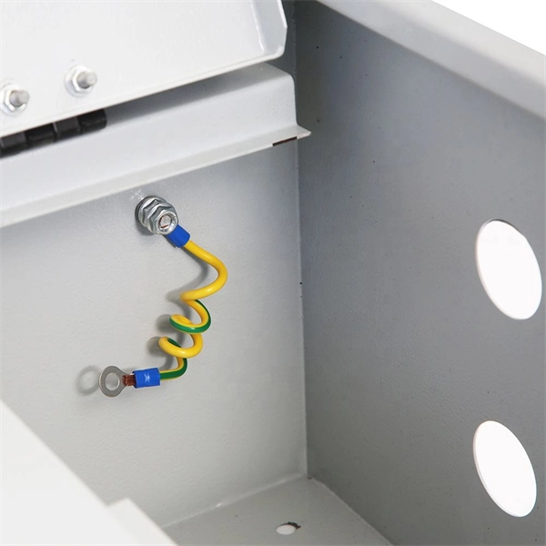
In Canadian service entrance panelboards the main switch or circuit breaker is located in a service box, a section of the enclosure separated from the rest of the panelboard, so that when the main switch or breaker is switched off no live parts are exposed when servicing the branch circuits.OverviewA distribution board (also known as panelboard, circuit breaker panel, breaker panel, electric panel, fuse box or DB box) is a component of an that divides an electrical power feed into subsidiary. North American distribution boards are generally housed in enclosures, with the positioned in two columns operable from the front. Some panelboards are provided with a door covering th. This picture shows the interior of a typical distribution panel in the United Kingdom. The three incoming phase wires connect to the busbars via a main switch in the centre of the panel. On each side of the panel are two.
[PDF]
In this video, we'll guide you through the process of configuring a Huawei Switch for your network. Whether you're setting up a new switch or optimizing your existing network infrastructure, this step-by-step tutorial will help you get the job done efficiently. This document provides campus networks typical configuration examples and feature typical configuration examples. "Campus Networks Typical Configuration Examples" provides typical campus network networking modes and a variety of deployment examples. This document is for switches running V200R003C00 and later. In this video, we'll guide you. Saving Configuration: Save changes to make the configuration permanent: Checking Settings: Use commands like display user-interface console 0 to verify correct configuration. Exiting the Device: Log out of the device after completing the configuration. Enabling Telnet Service and Granting Access on. The Combo interface, also known as the optical-electrical multiplexing interface, consists of two Ethernet ports (one optical and one electrical) on the device panel, and there is only one forwarding interface inside the device.
[PDF]
PoE delivers 44-57v of DC power over unshielded twisted-pair wiring for terminals consuming up to 25 watts, depending on the version of the standard in use. Power over Ethernet (PoE) describes any of several standards or ad hoc systems that pass electric power along with data on twisted-pair Ethernet cabling. This allows a single cable to provide both a data connection and enough electricity to power networked devices such as wireless access points. Imagine powering your entire network infrastructure through the same cables that carry your data, eliminating the need for separate power supplies and electrical outlets near every device. This isn't a futuristic concept—it's the reality that power over Ethernet has made possible since 2003. While PoE doesn't add Ethernet data capabilities, it does offer expanded options for how and where Ethernet end devices can be. Power over Ethernet is a technology that allows IP telephones, wireless LAN Access Points, security network cameras and other IP-based terminals to receive power, in parallel to data, over the existing CAT-5 Ethernet infrastructure without the need to make any modifications. The simple nature eliminates the need for multiple power supplies, and allows connectivity to devices where power outlets are not available. Instead of running a separate power line to each device, PoE lets the Ethernet cable (usually a Cat5e or Cat6 cable) carry both the network connection and.
[PDF]