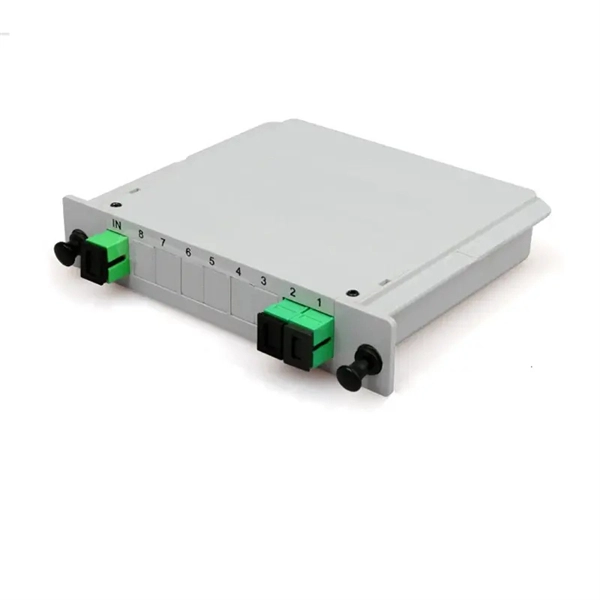
An Optical Distribution Frame (ODF) is a dedicated unit designed to organize, terminate, and interconnect fiber optic cables. It brings together fiber splicing, patching, and cable routing in a single structure, while shielding sensitive connectors and splices from mechanical. This complete guide explores everything you need to know about ODFs — from their structure, types, and key components, to installation best practices and modern design trends. Whether you're building a central office, data center, or FTTx distribution network, understanding the right ODF. An Optical Distribution Frame (ODF) is the central hub for fiber splicing, termination, patching, and cable protection in modern optical networks. Think of it as a big shelf where all your fiber cables come together, each tucked into a slot. The goal is to provide easy access, clear labeling, and fast repairs. This guide demystifies ODF, exploring their design, core functions, types, and how they.
[PDF]
Électricité du Laos (EDL; : ໄຟຟ້າລາວ) is the of that owns and operates the country's, and assets. The company also manages the and of from the of the country. EDL was founded in 1959 and is headquartered in. In July 2010, the loaned $15 million to Electricite du Laos for the expa.
[PDF]
IEC 61439 is a standard developed by the International Electrotechnical Commission (IEC) that covers design verification for low-voltage electrical products and assemblies. Busbar design within Medium Voltage (MV) switchgear is a critical aspect, fundamentally ensuring the safe, reliable, and efficient operation of power systems. The IEC 61439. Annex D was introduced in the april 2020 version of UL 508A. It clarifies what was previously common but not formally correct practice. A manufacturer of electrical automation panels is not required to use a certified busbar system or to subject it to short-circuit tests, provided that it complies. A recent study found that there are roughly 30,000 arc flash incidents in the United States each year, many of which are powerful enough to cause significant injury to workers and costly damage to equipment2. The adoption of busbar power distribution systems on a global scale has accelerated in the. Double spacer for easy leveling and connecting on both sides (snubber. ). From time to time we are asked what bus spacings are required by ANSI standards for switchgear. Those who ask are frequently surprised by the answer: None. ANSI switchgear standards are generally performance standards. Dielectric tests, power frequency withstand for all voltages and impulse.
[PDF]
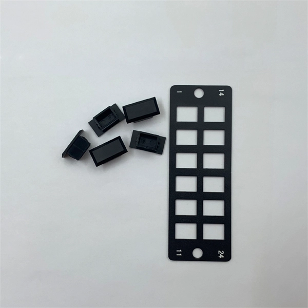
A splice box (also known as splice distributor) is a housing in which fiber optic cables begin or end. Fiber optics are fanned out in splice boxes that are situated at the end of fiber optic transmission paths. It typically consists of two parts: an outer housing and an internal structure. The main components of a splice box are the splice cassette that picks up the fibers and. The fiber optic dome splice closure is well-suited for splicing, distributing variable optical cables, and splitting. The solid box shell and the main structure are built to withstand harsh environments. The dome closure also protects fiber optic cables from vibration, impact, stretching, twisting. Home » Professional Insights » Fiber Optic Splice Closure: A Complete Guide to Types, Structure, Applications, and Selection In real fiber optic networks, cables are rarely installed as one continuous, uninterrupted length. Along transmission routes—whether in access networks, metro networks, or. Big space for managing pigtails or splitters. The 12 Port Fiber Distribution Box can connect up to 2 optical cables, providing space for distributors and 12 fuses. It is equipped with 12 SC adapters and can work in outdoor environments. Data communication networks. Horizontal fiber optic splice closures, also known as optical cable splice boxes, play an important role in the communications industry. It is a must-have device in the construction of optical cable line projects.
[PDF]
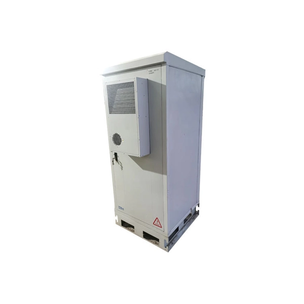
A wall-mounted distribution box is an electrical structure that is attached directly to a vertical surface. It usually holds control devices, 600V DC circuit breakers, and contactors. These small units are sealed on six sides and have pre-designed knockout points for cables to enter. Inside, you'll find parts like circuit breakers and fuses that protect the system from problems like overloads and short circuits. It ensures that electricity flows. 250A Distribution Board with Integrated Residual Current Protection! “What is a CBR?” In other words a CBR is the moulded-case circuit breaker equivalent of a DIN-modular RCBO - it includes overload, short-circuit and residual current protection inside a single device. How could a CBR give me a. ii) Busbars: Made of aluminum or copper, these bars distribute electric current from the main source to various circuits. Fuses melt under excessive current, while circuit breakers. ABSTRACT: Many factors affect the type and layout of power equipment. Ultimately, cost, resiliency, and maintainability will drive the equipment selection. Many companies are adopting zero energized work policies. Power. Then, without warning, a breaker overheats, a connection loosens, or moisture sneaks inside an outdated enclosure. Within minutes—production stops, servers glitch, alarms ring. These failures rarely come from “bad luck. ” They come from hidden vulnerabilities inside aging or poorly designed.
[PDF]
All efforts have been made to incorporate all relevant up to date information available, any discrepancies or need for addition or deletion is felt necessarily may please be intimated to this office for further i.
[PDF]
This study aims to develop a simple yet efficient performance-based design optimization methodology for cable tray systems in building structures. In the paper, the drift ratio between adjacent supports i.
[PDF]
This paper deals with a framework to support the design optimization of an overhead line using methods related to the theory of the Constraint Satisfaction Problem. The object-oriented model of a transmission line has been described and then implemented into a. INTRODUCTION: Artificial intelligence is a product of high-end technological development since the 21st century, which has subverted people's traditional cognition in many aspects and greatly enriched and improved people's lives. Artificial intelligence has covered every aspect of life, and the. OVERLAY VS. 50. The Power Distribution Overhead Line Monitoring System comprises sensors, concentrators, the data analytic platform, and AI algorithm modules. It is designed for real-time monitoring of power distribution lines, performing fault detection, fault waveform recording, fault section pinpointing, risk. This Design Manual sets out the requirements and must be applied to the design of an overhead distribution line in the ACT. It relates to the information necessary to assess various aspects of the development and its suitability for connection to Evoenergy's electricity system. SCOPE AND PURPOSE. In older distribution systems the supply authority collects the bulk energy at 66 kV or less from the transmission substation. As indicated in Figure 1 below, there are specific voltage values used in the distribution of electrical power.
[PDF]
To meet the needs of multi-way power distribution applied to high-power solid-state sources, a multi-way power distribution device based on coaxial waveguide is designed and studied. In this work, two dynamically tunable power dividers using waveguide ENZ media are proposed by precisely modulating the internal magnetic field and the widths of the output waveguides. The first approach features a mechanically reconfigurable ring-shaped ENZ waveguide. By analyzing the transmission characteristics of coaxial waveguides and by applying the theory of impedance. In this paper, an E -plane stepped-impedance transformer and Y-junction bifurcation are used to form a waveguide power divider with ceramic substrate loaded with thin film resistors. This structure is realized high isolation in V-band by inserting a ceramic substrate at the H -plane center of the. A numerical model of an equal power divider based on the 4-branch single-mode waveguide is proposed. This proposed design does not require extra fabrication process and supplementary structure modification compared to other typical multibranch waveguides. The condition of uniform output power.
[PDF]