In this guide, we will explore the significance of connecting PVC conduit to electrical boxes and provide you with a step-by-step process to accomplish this task effectively. Whether you're dealing with rigid metal conduit (RMC), PVC, or flexible conduit that's already in place, it can be removed or replaced, but there's no magic wand. You'll need to consider the type of conduit, the installation method, and. Electrical conduit fittings form the outer covering for most electrical wiring from one point to the next. They shield the wires from the external environment so as to make the wire last longer and also to keep humans and pets safe from electric shocks or other such vulnerabilities. The breaker box, or service panel, serves as the central distribution point, housing the circuit breakers that protect individual circuits from overcurrent conditions. Connecting made easy: How to effortlessly connect PVC conduit to electrical boxes! Installing electrical systems just got simpler with Ledes' seamless conduit connections! 💡. Firstly, it. Why Publish? How to Repair and Remove Conduit for Electric Wires: Let me teach you how to easily repair and remove conduit for electric wires. For the full guide and more tips read the post in 123 Do It Yourself blog: com/2014/01/22/22/.
[PDF]
The standard requirement for wire is 1. 5 to 2 feet for each square foot of the home; however, it may change depending on the project scope, needs, and demands. Whether you're quoting a panel upgrade for a new build or wiring a multi-unit commercial space, the numbers on your estimate aren't just guesses—they're the difference between staying profitable and bleeding hours on change orders. This guide lays out what it really takes to build accurate. In May 2026 the estimated national average cost to Install Electrical Wiring starts at $302 - $365 per wiring run. Use our Cost Calculator for cost estimate examples customized to the location, size and options of your project. Set Project Zip Code Enter the. It's natural to wonder about the bottom line, and understanding the electrical wiring cost per foot is the perfect place to start. When installed by a professional, this cost typically lands somewhere between $3 and $12. Here are the five steps to create a competitive electrical estimate. Early preparation. In electrical projects, preparing a professional electrical quote is an essential yet often time-consuming task. Calculating material costs, labor fees, and profit margins for electrical projects can be challenging, especially when meeting client expectations or managing revisions. The kitchen and the laundry area are the most power-consuming parts of the house.
[PDF]
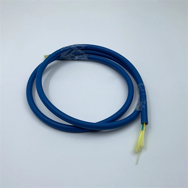
Wire color: The neutral wire is blue, and the color of the phase wire (A phase is yellow, B phase is green, and C phase is red) should meet the standard. Wire specification: Select the appropriate wire specification according to the circuit load. WARNING: Please be aware that the table below is a guide; a wire should never be identified by color alone. Wire color helps identify intent, not actual condition. Before handling any wire, always rely on testing with professional tools, not assumptions. Testing is the only reliable way to confirm. This guide describes wiring color codes, international standards, and main rules to keep in mind to work smarter and safer. The various colored wires that you can see when you look behind a switch or an outlet are not an accident, but rather a safety feature that is built in. For typical building AC circuits (commonly up to 600 volts nominal), the NEC specifies identification rules for grounded conductors (neutral), requirements. Electrical wiring color codes are a standardized system that tells electricians—and you—the specific job of every wire in the circuit. Getting this language right is the difference between a light that works and a dangerous situation involving short circuits, electrical shocks, or even fires. These color codes are used for electrical distribution systems, and while some are mandatory, others are optional. The lighting and socket circuits generally use.
[PDF]
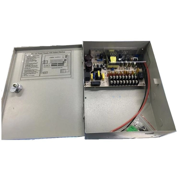
This video shows real on-site footage of electrical installation, demonstrating safe and standardized wiring methods used by professionals. more Learn how to wire a distribution box step by step! This video shows real on-site footage of. An electrical panel box, also known as a breaker box or a distribution board, is a crucial component of any electrical system. It serves as a central hub for distributing electricity throughout a building, ensuring that power is delivered safely and efficiently to all the required locations. Proper grounding, insulation, and connection of wires are essential to maintain the integrity of the electrical system. Here are some key reasons why proper wiring is crucial in a 3 phase DB box: Prevention of Electrical Hazards: Proper wiring ensures that electrical currents flow smoothly and. Ensure safe placement: install in dry, accessible areas with good ventilation and at appropriate height (typically ~1. Whether you're a professional or a DIY enthusiast, understanding the correct procedure can prevent accidents and ensure optimal performance. This guide provides step-by-step. Hey, in this article we are going to see the Single Phase Distribution Box Wiring Diagram and Connection Procedure. And all the switching and protective devices are installed in the.
[PDF]
A neat, well-organized subpanel bundles wires to conserve space and improve access. Ideally, wire groups are installed in layers and wires are bent at right angles to buses or breakers. Label short sheathing sections (slugs) to indicate which circuits wires serve. Choose the right box based on environment (indoor/outdoor), load capacity, and durability. Check for proper IP/NEMA ratings and material quality. Ensure safe placement: install in dry, accessible areas with good ventilation and at appropriate height (typically ~1. Practice good wiring: secure. Box installation: Make sure that Distribution box has been correctly installed and fixed. Material preparation: Prepare the required circuit breakers, wires, wiring ties and other materials, and ensure that they meet the design drawings and installation requirements. And all the switching and protective devices are installed in the. Wiring distribution panels serve as the central hub and nerve center, routing power from the main service feed to multiple circuits. When setting up such a significant component of industrial, commercial, and utility applications, it's essential to get everything right. Labeling cables at outlets is.
[PDF]
Check the electrical load and ensure that the sensors do not exceed the 10 Amp maximum. Replace any damaged cables. Check the tightness of electrical connections along the. That is why electrical energy distribution troubleshooting is critical in homes, businesses, and industrial sites. It helps identify faults early and prevents costly downtime. A clear troubleshooting process ensures power flows safely and efficiently. In this guide, you will learn how distribution. An electrical panel box, also known as a breaker box or a distribution board, is a crucial component of any electrical system. When devices in your new box don't work, you start by testing the circuit. You will want a voltage tester (doesn't need to be a voltmeter) for this job. The very cheapest one you can find at a local hardware store (or online) will work great. When they start tripping, overheating, or making strange noises, it's more than just an inconvenience - it's your home's cry for help. You need to know how to diagnose the fault in a low voltage distribution box safely.
[PDF]
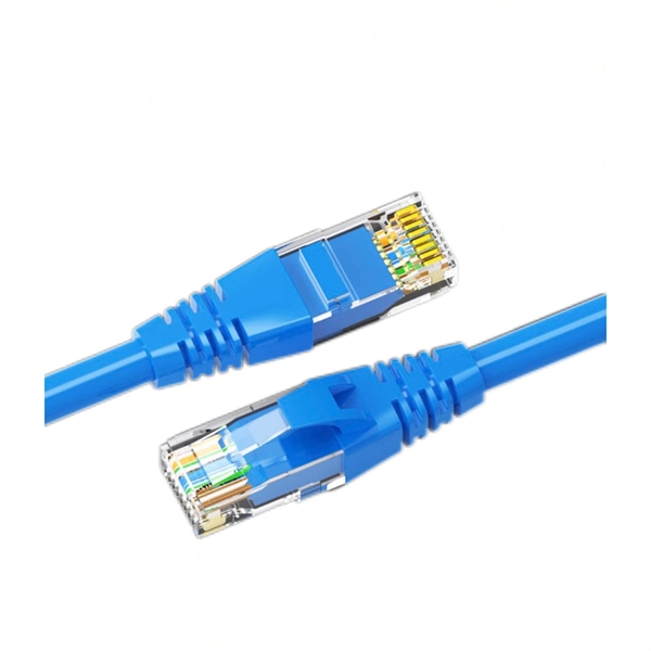
Rack Elevation or Server Rack Layout Software are simple tools to plan and document the cabling of your server cabinet. To make it even easier for you, we launched the free online Rack Planner. It helps you create a helpful rack diagram and keep your network tidy. Network cabinet cabling describes the structured connection and arrangement of all IT components in a server rack. The aim is a secure, maintainable and scalable operation of the network environment. Step-by-step guide: In this way, patch panels, switches, cable routing and documentation are. Creating a rack diagram is an important step to having sustainable good cable management in the network cabinet. Let's take a look at the essential components, selection criteria, and best practices for efficiency, order and protection of the network. Use cabinet screws to fix the network patch panel to the network cabinet. Note the wiring sequence on the patch panel when wiring, as T568A and T568B have different sequences. Wiring a server or network rack feels simple at first. Cables plug in, and devices turn on. Then problems appear. Slow speeds and tangled wires with card troubleshooting. Clean wiring prevents those issues before they start.
[PDF]
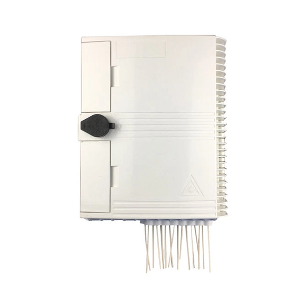
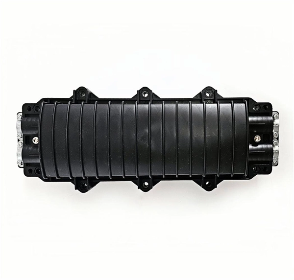
In network cabling, outdoor connections generally use fiber optic cables. When these optical fibers are installed or laid out, a Fiber Termination Box, or FTB, is used to distribute and protect the optical fiber link.
[PDF]
(1) The admissible load of a complete system depends on the system topography and the application parameters. Factors of influence are ambient temperature, air circulation, busbar load, distribution of busbar loa.
[PDF]

Optical splitters enable a signal on an optical fiber to be distributed among two or more fibers. Since fiber splitters contain no electronics nor require power, they are an integral component and widely used in most fiber-optic networks. A fiber optic splitter is a passive optical component that divides a single incoming optical signal into two or more outgoing signals, or combines multiple incoming signals into one. Unlike active devices (which require power), splitters operate without electricity, relying solely on the physics of. Optical cables, also known as fiber optic cables, consist of thin strands of glass or plastic fibers surrounded by a protective casing. These fibers transmit data as light signals, which are converted into electrical signals at the receiving end. The benefits of optical cables are numerous. A fiber-optic splitter, also known as a beam splitter, is based on a quartz substrate of an integrated waveguide optical power distribution device, similar to a coaxial cable transmission system. Its primary role is in Passive Optical Networks (PON), which are the foundation of. A fiber broadband provider typically determines and overall split ratio for the network, such as 1x32 or 1x64, and uses combinations of splitters to meet that ratio with each PON port. 1x32 splits were common in North America for G-PON architectures. As XGS-PON continues to be adopted, some service.
[PDF]
Optical modulators are used in optical communication systems to encode data onto light waves for transmission through optical fibers. The modulator encodes the data onto the light wave by modifying its amplitude, phase, or frequency. 📦 For purchasing, use the RP Photonics Buyer's Guide for optical modulators. It provides an expert-curated supplier directory, buyer-focused technical background information, and structured selection criteria to support professional procurement decisions. What are Optical Modulators? An optical. Optical modulators are devices that modify the properties of light, such as its amplitude, phase, frequency, or polarization, in response to an external signal. These devices play a crucial role in modern optics and photonics, enabling the manipulation of light for various applications. The beam may be carried over free space, or propagated through an optical waveguide (optical fibre). It acts as the “translator” between the electronic and photonic worlds. They enable the modification of optical wave characteristics such as the intensity, phase, polar-ization, and frequency of light signals. There are basically two types of modulators: bulk and integrated-optic.
[PDF]
Instead of fusing one fiber at a time, mass fusion splicing can fuse up to all 12 fibers in one ribbon at once. Many of today's cables with high fiber count involve subunits of 12 fibers each that can be quickly ribbonized. Fiber optic joints or terminations are made two ways: 1) splices which create a permanent joint between the two fibers or 2) connectors that mate two fibers to create a temporary joint and/or connect the fiber to a piece of network gear. Either joining method must have three primary characteristics. Fiber optic splicing is the process of seamlessly joining two single Splicing has a lower optical loss and back-reflection than other terminations, making it the ideal choice for maintaining signal integrity and reliability in fiber optic networks. There are numerous use cases for fiber optic splicing. Through splicing, fiber optic technicians can extend the length of the fiber to make it long enough for use in a required cable run. As. To begin, the standard definition of splicing in optical fiber is joining two fiber optic cables together. The other, more common, method of joining fibers is called termination or connectorization. Splicing is most commonly used in the field but has application in cable assembly houses.
[PDF]
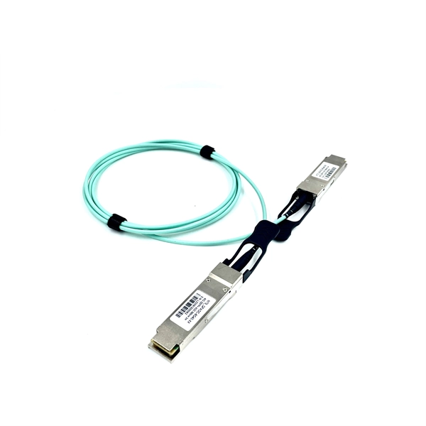
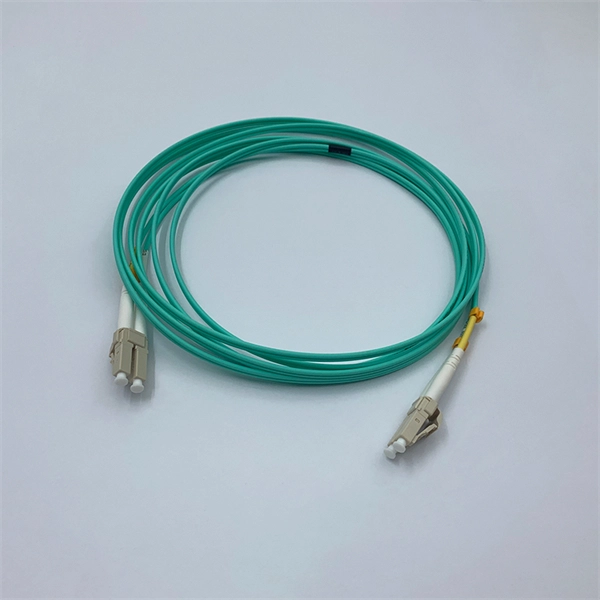
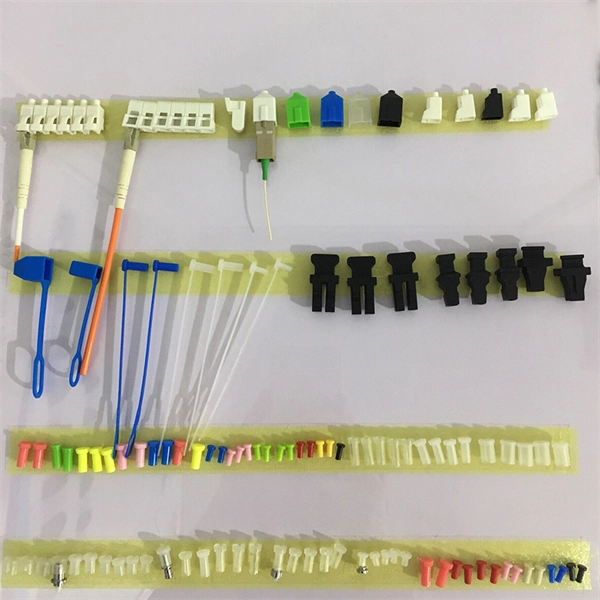
The most commonly used patch cable connectors today include FC, ST, SC, LC, MTRJ, and MPO connector types, as well as newer very small-form-factor (VSFF) CS, SN, and MDC connectors used in high-density, high-speed duplex data center environments. This guide will help you quickly understand the main types of fiber patch cords and how to choose the right solution for your project – and how ZION can support you with stable quality, flexible customization and global supply. What Is a Fiber Optic Patch Cord? A fiber optic patch cord (fiber. An optical fiber patch Cable is a jumper wire used to connect from equipment to an optical fiber cabling link, and it is usually used for the connection between an optical transceiver and a terminal box. It is widely applied in fields such as optical fiber communication systems, optical fiber. Fiber optic patch cords, also known as fiber optic patch cables or fiber jumpers, are indispensable components in modern optical networks. They act as the critical link for interconnecting devices like optical switches, servers, and distribution frames. Behind its slender appearance lies the fusion of core types, connector types, and polish levels, each chosen for a specific application. It is composed of fiber optic cable and fiber connector that fixed at both ends of optical cable, has been widely used in various fields such as fiber optic.
[PDF]
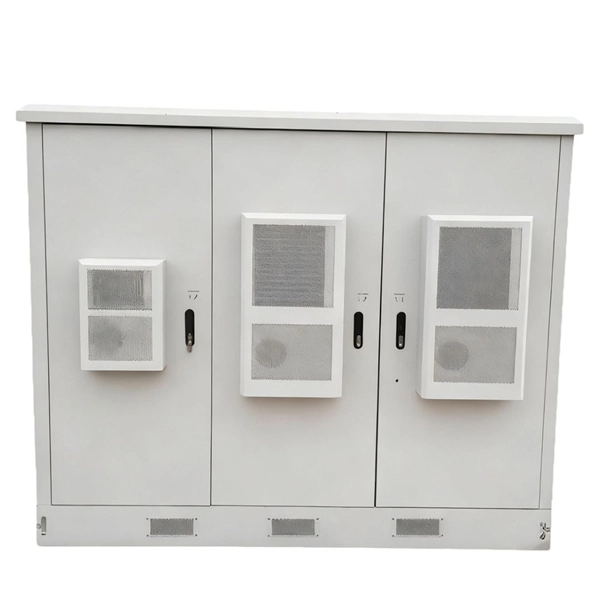
Fiber distribution box, also known as fiber optic distribution frame, is an essential component in fiber optic communication networks. It plays an important role in organizing, managing, and protecting fiber optic cables, ensuring reliable and efficient network operations. With features like IP68 waterproof ratings, fast connectors, and hardened adapters, distribution boxes enhance data transmission by offering proper termination points and environmental protection. It provides a secure space where incoming fiber optic cables from the provider's network are. A fiber distribution cabinet is a key component in modern fiber optic networks, designed to manage, protect, and distribute optical fibers efficiently. It serves as a central point where fiber cables are terminated, spliced, and organized for further connection to end users. The distribution box provides.
[PDF]

This document provides a comprehensive technical overview of the Ring Main Unit (RMU), serving as a reference for power system design, selection, and maintenance. Ring Main Units (RMU s) and Medium Voltage (MV) Switchgear are crucial in MV power distribution. Globally, they each hold about half the market share. MV switchgear handles primary distribution for large industrial facilities and grid infrastructure. RMUs, however, shine in secondary distribution. RMUs are commonly used in secondary distribution systems, particularly in urban areas, industrial complexes, and commercial. Scope of Application: The Ring Main Unit (RMU) is a compact switchgear device used in medium-voltage power distribution systems (typically 10kV–35kV). Some of the key features of the RMU includes SF6 gas insulation, compact and modular construction, integral protection system, fully extendable options. SFA-RM units are designed for supplying reliable energy, protecting electrical equipment in secondary distribution networks up to 17. Their compact design makes them suitable for various network applications such. Loading. Company Introduction:The New Concept Electric Inc. (NCE) was founded in October 2001, with a registered capital of 57 million Yuan. The company now covers an area of 77, 601 square meters (116 acres), and has a building area of 80, 451 square meters.
[PDF]