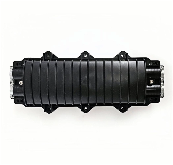
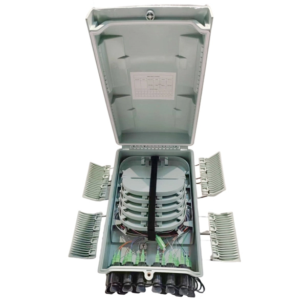
In network cabling, outdoor connections generally use fiber optic cables. When these optical fibers are installed or laid out, a Fiber Termination Box, or FTB, is used to distribute and protect the optical fiber link.
[PDF]
(1) The admissible load of a complete system depends on the system topography and the application parameters. Factors of influence are ambient temperature, air circulation, busbar load, distribution of busbar loa.
[PDF]
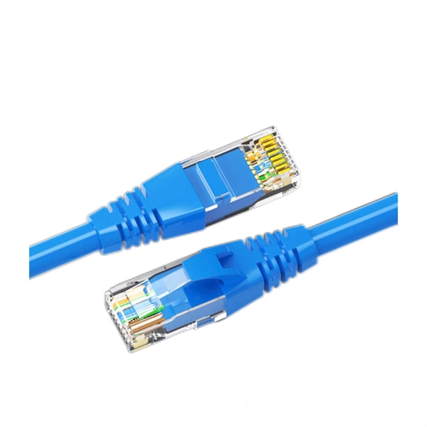
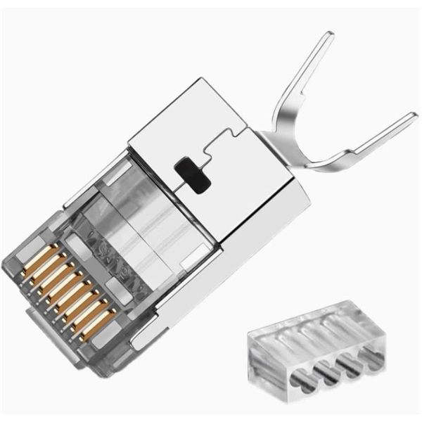
Rack Elevation or Server Rack Layout Software are simple tools to plan and document the cabling of your server cabinet. To make it even easier for you, we launched the free online Rack Planner. It helps you create a helpful rack diagram and keep your network tidy. Network cabinet cabling describes the structured connection and arrangement of all IT components in a server rack. The aim is a secure, maintainable and scalable operation of the network environment. Step-by-step guide: In this way, patch panels, switches, cable routing and documentation are. Creating a rack diagram is an important step to having sustainable good cable management in the network cabinet. Let's take a look at the essential components, selection criteria, and best practices for efficiency, order and protection of the network. Use cabinet screws to fix the network patch panel to the network cabinet. Note the wiring sequence on the patch panel when wiring, as T568A and T568B have different sequences. Wiring a server or network rack feels simple at first. Cables plug in, and devices turn on. Then problems appear. Slow speeds and tangled wires with card troubleshooting. Clean wiring prevents those issues before they start.
[PDF]
Wire color: The neutral wire is blue, and the color of the phase wire (A phase is yellow, B phase is green, and C phase is red) should meet the standard. Wire specification: Select the appropriate wire specification according to the circuit load. WARNING: Please be aware that the table below is a guide; a wire should never be identified by color alone. Wire color helps identify intent, not actual condition. Before handling any wire, always rely on testing with professional tools, not assumptions. Testing is the only reliable way to confirm. This guide describes wiring color codes, international standards, and main rules to keep in mind to work smarter and safer. The various colored wires that you can see when you look behind a switch or an outlet are not an accident, but rather a safety feature that is built in. For typical building AC circuits (commonly up to 600 volts nominal), the NEC specifies identification rules for grounded conductors (neutral), requirements. Electrical wiring color codes are a standardized system that tells electricians—and you—the specific job of every wire in the circuit. Getting this language right is the difference between a light that works and a dangerous situation involving short circuits, electrical shocks, or even fires. These color codes are used for electrical distribution systems, and while some are mandatory, others are optional. The lighting and socket circuits generally use.
[PDF]
In this video we are showing a complete Construction Site Electrical Distribution Panel setup. This includes MCCB, MCB, DB boxes, cable management, earthing and load distribution for machines. This. Through a real-world project scenario, we explore how structured connectors, IP67 plug systems, and modular distribution cabinets create safer, faster, and more reliable temporary electrical infrastructure. Temporary Power Should Never Mean Temporary Safety Construction sites rely heavily on. Insulation Tools: Ensure that wires and cables are properly insulated to prevent electric shocks. Training and education are key components of safe temporary electrical installations on construction sites. Workers need to be aware of the risks and know how to handle electrical equipment safely. Overhead Cables: Overhead supply from the supply point or metering point to the distribution boards on the site should be of a robust pattern. These regulations place a requirement on every employer to assess every work activity in order to identify any hazard that employees or any other person might encounter as a result of the work being carried out. HSE document INDG 163 gives advice on these regulations. The Provision and Use of work. If it's done poorly, you risk short circuits, fire hazards, or system failure. Done right, it ensures safety, compliance, and long-lasting performance. Choose the right box based on.
[PDF]
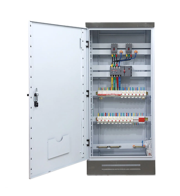
In this video, we'll walk you through the process of wiring a home distribution box with a detailed connection diagram. Whether you're an electrician or a DIY enthusiast, this guide will help you understand the basics of home electrical distribution. more Welcome to our channel! In this video. How to wire a household distribution box? How to pg clamps. When it comes to decoration, many friends like to do it themselves. However, when encountering water and electricity and other links that have a greater impact on the overall decoration, you must do your homework and not implement it. An electrical panel box, also known as a breaker box or a distribution board, is a crucial component of any electrical system. It serves as a central hub for distributing electricity throughout a building, ensuring that power is delivered safely and efficiently to all the required locations. Distribution Board or DB is an electricity supply system or a common enclosure that distributes the electrical power feed into subcircuits. What is Distribution Board? Distribution board. A distribution board or distribution box is where the main power supply is distributed to multiple loads. And all the switching and protective devices are installed in the distribution box. Single Phase Distribution Box generally consists of Double Pole MCBs, Single Pole MCBs, and RCCBs.
[PDF]
Key cost drivers include panel amperage, indoor vs outdoor location, wiring length, and whether a full panel upgrade or rerouting is needed. The article outlines cost ranges, per-unit pricing, and practical budgeting notes for U. Buyers typically pay for a full panel replacement, including labor, materials, and permits. Improper electrical work often leads to fires, shocks, or health problems such as nerve damage. You may face expensive repairs if you skip steps or ignore safety rules. The main drivers are panel capacity, existing wiring condition, permit requirements, and whether anyUpgrade to. An electrical panel box, also known as a breaker box or a distribution board, is a crucial component of any electrical system. It serves as a central hub for distributing electricity throughout a building, ensuring that power is delivered safely and efficiently to all the required locations. In this guide, we'll break down everything you need to know to install a distribution box correctly and confidently. Choose the right box based on environment (indoor/outdoor), load capacity, and durability. Ensure safe placement: install in. Learn how to wire a distribution box step by step! This video shows real on-site footage of electrical installation, demonstrating safe and standardized wiring methods used by professionals.
[PDF]
In this comprehensive guide, we'll walk you through the fundamentals of frame wiring and embedding, including the techniques, materials, and best practices you need to know. We'll also cover important safety considerations and troubleshooting methods to help you identify and fix common issues. By. Framing an electrical panel involves constructing a decorative or protective structure around the existing breaker box, typically to improve the aesthetics of an unfinished space. This project transforms a utilitarian component into a visually integrated part of the wall while ensuring the panel. What is the most efficient way to rough in wiring and later install receptacles in the back of cabinetry for built-in appliances? In the past I have just left whips and then come back and cut in the receptacle. But it's a pain because you're hunched into the cabinet opening doing the work. Cut and install a plywood frame using an electric saw, securing it to the wall studs. Paint the frame to match the surrounding wall for a seamless look. The purpose of this presentation is to introduce some practical methods on how to reduce disturbances in order to avoid EMC problems and not how to meet the EMC standards. EMC is the ability of electronic equipment to operate without problems within an electromagnetic environment. Equipment must.
[PDF]
This video shows real on-site footage of electrical installation, demonstrating safe and standardized wiring methods used by professionals. more Learn how to wire a distribution box step by step! This video shows real on-site footage of. An electrical panel box, also known as a breaker box or a distribution board, is a crucial component of any electrical system. It serves as a central hub for distributing electricity throughout a building, ensuring that power is delivered safely and efficiently to all the required locations. Proper grounding, insulation, and connection of wires are essential to maintain the integrity of the electrical system. Here are some key reasons why proper wiring is crucial in a 3 phase DB box: Prevention of Electrical Hazards: Proper wiring ensures that electrical currents flow smoothly and. Ensure safe placement: install in dry, accessible areas with good ventilation and at appropriate height (typically ~1. Whether you're a professional or a DIY enthusiast, understanding the correct procedure can prevent accidents and ensure optimal performance. This guide provides step-by-step. Hey, in this article we are going to see the Single Phase Distribution Box Wiring Diagram and Connection Procedure. And all the switching and protective devices are installed in the.
[PDF]
All wiring in hoistway and in equipment room shall be of a type identified by CEC 620. Please add appropriate notes. Separate branch circuits are needed for car lights, receptacle outlets, and ventilation. The purpose of this T/C is to clarify wiring that is permitted to be located in an elevator hoistway, machine/control room, or control space/room. Minimizing the need for. These requirements, found in Article 620 (part of Chapter 6, Special Equipment), are in addition to NEC Chapters 1-3, which stipulate general wiring protocols applicable in most residential, commercial and industrial venues. The code exempts some fairly broad areas where compliance is not expected. In Oregon, Raceways and conduits for the connection of elevator devices shall only enter the machine room to the extent necessary to connect the devices attached thereto. 37 covers wiring in hoistways, machine rooms, control rooms, machinery spaces, and control spaces related to the. By General Contractor / Owner Each home elevator requires five (5) items from your Electrician and Telecommunications Contractor(s). They are as follows: One (1) GFI Outlet. One (1) Light Fixture (with protective cover over bulb) with wall switch. One (1) Live Land Based Phone Line with pigtail. Main Power - 10/3 with Ground (min. 6”) pigtail connected to house 30 Amp dedicated circuit. 240VAC for LLH REQUIRES neutral. One (1) GFI Outlet separate from #2 elevator (120VAC) circuit.
[PDF]
A neat, well-organized subpanel bundles wires to conserve space and improve access. Ideally, wire groups are installed in layers and wires are bent at right angles to buses or breakers. Label short sheathing sections (slugs) to indicate which circuits wires serve. Choose the right box based on environment (indoor/outdoor), load capacity, and durability. Check for proper IP/NEMA ratings and material quality. Ensure safe placement: install in dry, accessible areas with good ventilation and at appropriate height (typically ~1. Practice good wiring: secure. Box installation: Make sure that Distribution box has been correctly installed and fixed. Material preparation: Prepare the required circuit breakers, wires, wiring ties and other materials, and ensure that they meet the design drawings and installation requirements. And all the switching and protective devices are installed in the. Wiring distribution panels serve as the central hub and nerve center, routing power from the main service feed to multiple circuits. When setting up such a significant component of industrial, commercial, and utility applications, it's essential to get everything right. Labeling cables at outlets is.
[PDF]
This video shows real on-site footage of electrical installation, demonstrating safe and standardized wiring methods used by professionals. However, exposure to weather, frequent relocation, rough use and other condi-tions not normally encountered with conventional wiring systems necessitate special consideration not require in other applications or in completed structures. The. A distribution box is the heart of any electrical system. It takes the incoming power and safely distributes it to different circuits throughout your building. Whether in a home or an industrial facility, this box keeps your electrical setup organized, functional, and efficient. However, the key to. Temporary power systems are essential for construction projects, yet they often introduce serious safety risks. Loose wiring, exposed connectors, and unstable electrical connections can cause shocks, equipment failures, or costly downtime. This article examines how modern portable power cabinet. Conductors entering boxes, cabinets, or fittings. Conductors entering boxes, cabinets, or fittings shall be protected from abrasion, and openings through which conductors enter shall be effectively closed. Covers and. Whether you are an electrical contractor or a construction brigade, knowing how to properly and safely install distribution boxes is the basis of ensuring the safe operation of the entire system. This article details the process of installing them, which helps you comprehend distribution boxes.
[PDF]
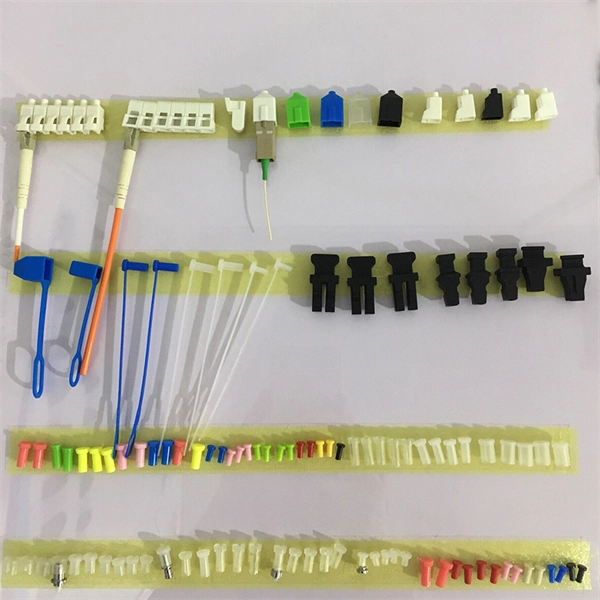
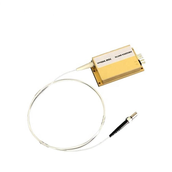
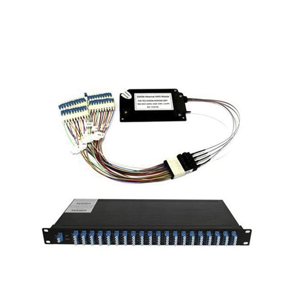
Fiber optic pigtails are short, single, or multi-strand pieces of optical fiber cables with a connector on one end and exposed fiber on the other end. They are typically used to terminate fiber optic cables and connect them to patch panels, equipment, or other termination points. This comprehensive guide aims to demystify fiber optic pigtails, exploring their design, functionality, and the myriad of applications they serve in today's technology-driven world. It is usually suitable for field termination using a mechanical or fusion splicer. Compared with quick termination or epoxy and polish connections placed on the field. Fiber pigtails are simple in appearance, yet essential in function. By combining factory-installed connectors with spliced bare fiber, pigtails ensure that network installers can create. Executive Summary: A fiber optic pigtail is one of the most commonly specified yet least understood components in structured cabling. Get the wrong connector type, the wrong polish, or skip proper fusion splicing technique—and you're looking at elevated signal loss, increased back reflection, and a. A key component in fiber optic systems is the fiber optic pigtail, a small yet indispensable part of the overall networking architecture. This unique design is the key to seamless integration with a variety of optical devices, ensuring signals traverse with.
[PDF]
Use pigtails when connecting multiple wires to a single terminal, upgrading outlets or switches, or managing crowded electrical boxes. Pigtails play a crucial role in ensuring safe and efficient connections within electrical systems, especially when dealing with multiple wires or limited space. Understanding what a pigtail is and how it works can make your wiring projects smoother and safer. ” This method is especially useful when connecting wires to devices such as switches, outlets, and junction boxes, allowing. Proper using pigtails breaks this chain. By creating independent pathways, technicians isolate problems without shutting down complete circuits. Commercial buildings using this method report 83% faster troubleshooting times. The National Electrical Code mandates continuous neutral connections in. Optical fiber pigtails are short optical fibers used to connect fiber optics with other equipment (such as optical modules, splitters, etc. ), typically used in fiber optic networks. With advantages such as low insertion loss, high return loss, good interchangeability, and repeated plugging. A pigtail in electrical wiring is a short length of conductor used to transition from a bundle of multiple circuit wires to a single termination point, such as a device terminal or fixture connection. This technique is often employed when three or more wires need to be joined, ensuring that the.
[PDF]
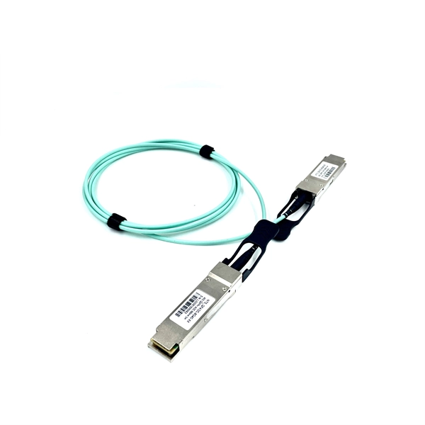
Learn the key difference between pigtail and jumper cables: only one end of a pigtail connects, while both ends of a jumper feature connectors. Similar to coaxial cable, but without mesh shielding, for jumper. When it comes to fiber optics, we naturally think of patch cords and pigtails. Usually people don't know the difference between the two. Let's find out together. Carrier-grade single-mode fiber patch. The Fiber Optic Patch Cord, also referred to as a fiber optic patch cable or fiber jumper, is a specialized cable designed for transmitting data signals using light waves in fiber optic communication systems. It is worth noting that fiber pigtails and patch cords are not the same concept. The main difference between fiber optic patch cords and fiber optic pigtails is that only one end of the fiber optic pigtail has an active connector, and both ends of. Jumper cables and portable jumper boxes are both tools used to revive a vehicle with a dead battery, but they have distinct differences despite sharing a similar end-goal. And with a plethora of purchasable options in both camps, it can be difficult to decide which way to spend your pretty pennies.
[PDF]