Trim solid or stranded wire to length and insert into clamp-style terminals. Tighten with a screwdriver. Tug on all connections to make sure they are secure. Close up electrical boxes. Turn on the power and check your work. Learn how to wire a distribution box step by step! This video shows real on-site footage of electrical installation, demonstrating safe and standardized wiring methods used by professionals. Make sure the power's off using a non-contact voltage tester or multimeter. One final tip: Get into the habit of making connections in this. This guide provides step-by-step instructions for connecting a distribution box and highlights key factors to consider during installation. What Is a Distribution Box? A distribution box, also known as an electrical distribution board, is a critical component in electrical systems. It serves as a. Material preparation: Prepare the required circuit breakers, wires, wiring ties and other materials, and ensure that they meet the design drawings and installation requirements. Choose the right box based on environment (indoor/outdoor), load capacity, and durability. Check for proper IP/NEMA ratings and material quality. Beginning of dialog window. Escape will cancel and close the window. This modal can be closed by pressing the Escape key or activating the close button.
[PDF]
Where single conductor cables comprising each phase, neutral, or grounded conductor of an alternating-current circuit are connected in parallel as permitted in 310. Joining conductors in parallel is like having two or more smaller conductors connected at each end to make one larger conductor. The single input supply (phase and neutral) is connected to this main MCB. When this MCB is turned on all other MCBs will get the power supply. Single-pole MCBs are used for the output loads. The isolator is used to OPEN and CLOSE the lines manually, which is the main switch of the electrical system. The RCCB is a device used. These are usually connected to thick black or red wires, each carrying 120V in a split-phase system. Verify voltage with a multimeter: each line wire should show ~120V to neutral and ~240V across both hot wires. Load terminals, positioned below the line lugs, distribute current to downstream. What's a neutral?The IEEE defines a Neutral as the conductor that has an equal potential difference between it and all other conductors (hot wires). An example of a neutral wire would be the white/gray wire of a single-phase 120/240 volt system or a three-phase 4-wire Wye system, Figure 1-1. 10 (G) (2) through (G) (6).
[PDF]

Thinner cables can be utilized to connect the control switch to the relay; this saves space, weight, and cost. The same voltage and current ratings as other types of switches, such as mechanical switches, do not limit relays. This handbook covers the code of practice in protection circuitry including standard lead and device numbers, mode of connections at terminal strips, colour codes in multicore cables, dos and donts in execution. Also principles of various protective relays and schemes including special protection. A control relay is an electrically operated switch that enables current to flow through a coil that closes or opens the switch. Relays use a small current to control a larger current, making them ideal for controlling high-power devices such as motors, lights, valves, and sensors. When a relay contact is open, this will switch power ON for a circuit when the coil is activated. You'll connect a low-power control circuit to the relay's coil (terminals 85 and 86), which then flips a switch for a separate, high-power circuit running through the. Electrical protection relay has two type protecton as HT panel protection and LT panel protection. HT panel protection relay. The HT power supply is received from GO switch and distributed to the. The rectangular devices are test connection blocks, used for testing and isolation of instrument transformer circuits. : 4 The first protective relays were electromagnetic.
[PDF]
This guide will provide you with a detailed Cat 6 socket wiring diagram, outlining the necessary steps and components required for a successful installation. If you want to install a classic network socket, you must first strip the Cat. A special stripping tool for data cables is used here – for example, the Stripper No. Use side A to remove the protective jacket. 35, you can shorten the network cable (Cat. 7) a little bit, if required. If you have too much cable left, it will be harder to. Learn how to wire a distribution box step by step! This video shows real on-site footage of electrical installation, demonstrating safe and standardized wiring methods used by professionals. 5mm² wires, and the air conditioning circuit can use 2. Connection method: Each switch takes a wire from the incoming point and connects it to the incoming end of the switch, or uses parallel connection to reduce the difficulty. Learn how to install a distribution box safely and correctly. Covers wiring, placement, standards, and expert tips for a compliant setup. A distribution box is the heart of any electrical system. It takes the incoming power and safely distributes it to different circuits throughout your building. Understanding the wiring diagram of an electrical panel box is essential for electricians and homeowners alike, as it allows them to troubleshoot any electrical issues, carry out repairs, or make additions to the system.
[PDF]
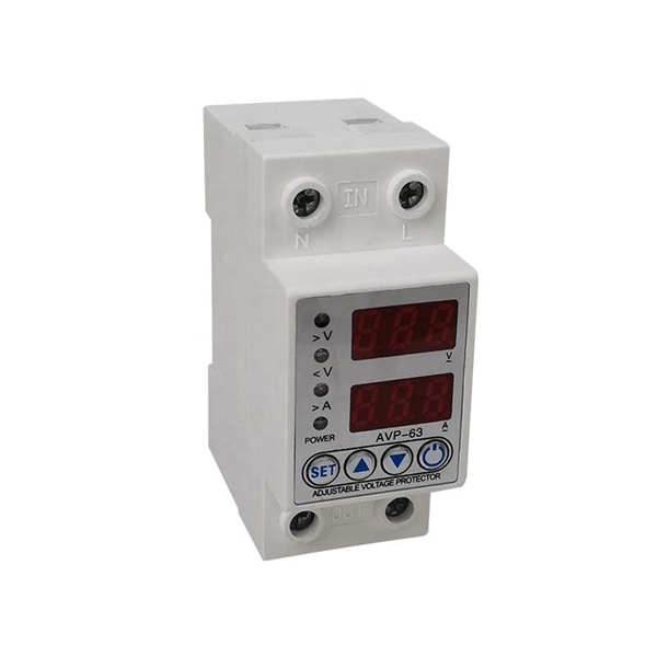
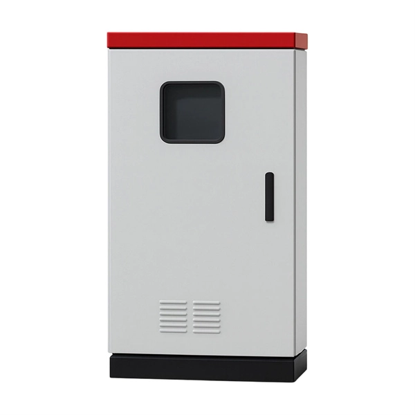
Live (L) Wire Connection: In a distribution box setup, the incoming live wire (also known as phase or hot wire, denoted as L or Line) connects to the line terminal of the circuit breaker. This serves as the primary source of electrical energy from the mains supply. Correct wiring methods for circuit breakers within distribution boxes are fundamental to ensuring electrical safety and compliance with established codes. The distinction between 1P and 2P circuit breakers plays a pivotal role in determining the appropriate protection level for various circuits. And all the switching and protective devices are installed in the distribution box. Single Phase Distribution Box generally consists of Double Pole MCBs, Single Pole MCBs, and RCCBs. The wire neutral is the return line in an electrical system that brings current from the electrical equipment back to the transformer or distribution box, completing the loop closure of the current. Figure 2-3 What wire is neutral? What does the neutral wire do? Although the neutral wire is usually. Live wires carry the power from the source to a switch or appliance. These may be light switches, electrical outlets, or junction boxes for light fixtures. The live wire is always under voltage, meaning it carries the. The main service panel, also known as the breaker box, is the central distribution point for the home's electrical system.
[PDF]
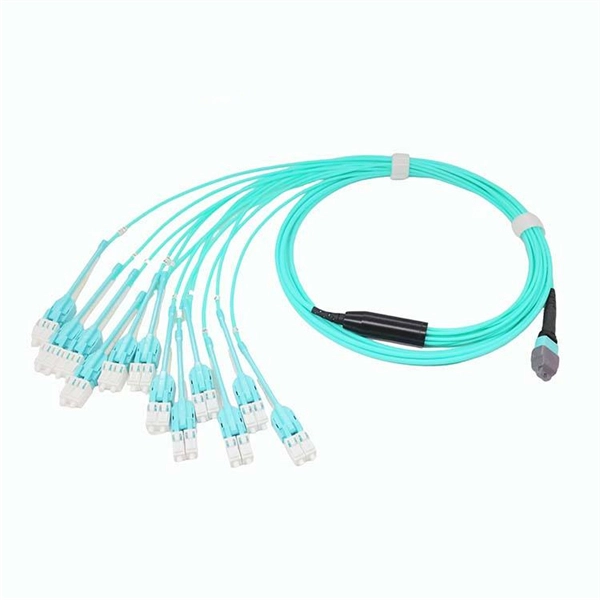
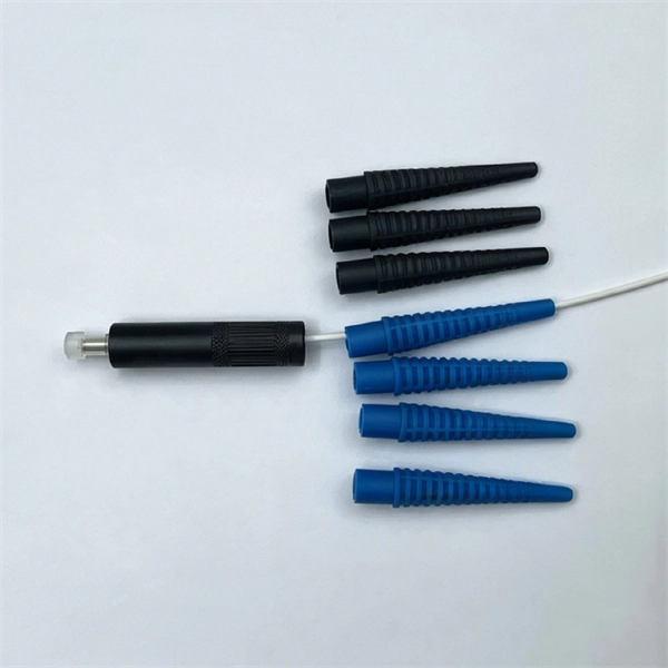
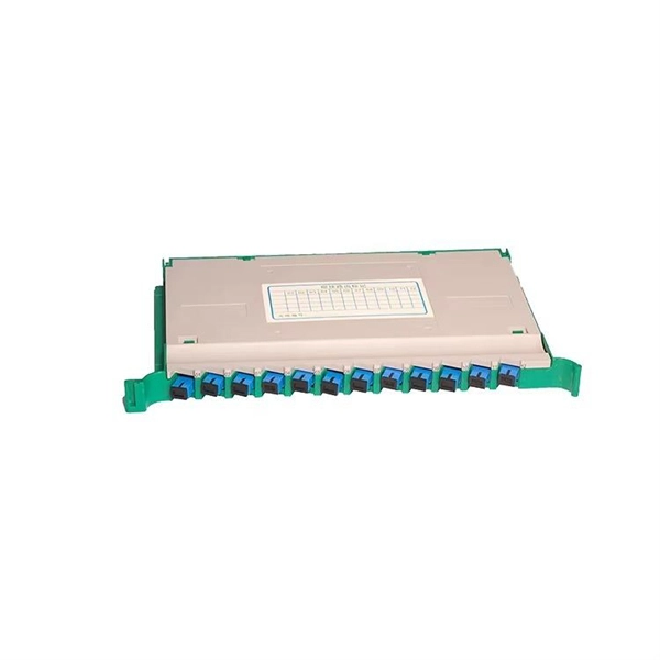
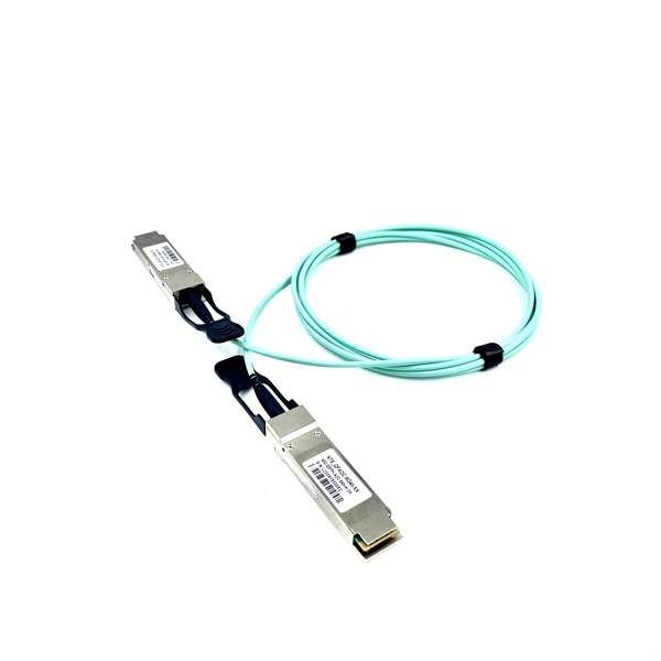
Fiber optic patch cables are ideal for supporting high speed telecommunication network fiber applications. They are manufactured and tested in compliance with TIA 604 (FOCIS), IEC 61754 and YD/T industry s.
[PDF]
These specialized trays are designed using non-combustible materials, often rated according to international standards such as UL 94 and IEC 60332. Fireproof cable trays provide a controlled pathway for electrical cables while also providing excellent resistance to heat and flames. NewReach has created a fire-rated cable tray designed to maintain its structure during a fire. This tray effectively prevents the spread of flames for a specified duration. Its design supports cables and equipment, helping to ensure they do not collapse in the event of a fire. The proper coating and acceptance of fireproof cable trays are essential for long-term performance and safety. For electrical contractors, the installation of fire-resistant cable trays is not just about organizing. Fire resistant cable trays are cable trays with fire-resistant boards as the core protective layer. A cable tray may comply with a product standard, an installation code.
[PDF]
Each wire must connect to its appropriate terminal: Live wires (red or brown) connect to the MCB's live terminal. Neutral wires (black or blue) go to the neutral bus bar. Welcome to our channel! In this video, we'll walk you through the process of wiring a home distribution box with a detailed connection diagram. Whether you're an electrician or a DIY enthusiast, this guide will. This guide provides step-by-step instructions for connecting a distribution box and highlights key factors to consider during installation. What Is a Distribution Box? A distribution box, also known as an electrical distribution board, is a critical component in electrical systems. In Single Phase supply (230V in UK, EU and 120V & 240V in the US & Canada), there are two (one is Line (aka Phase, Hot or Live) and the other one is Neutral) incoming cables from the utility poles to the kWh energy. A distribution board or distribution box is where the main power supply is distributed to multiple loads. And all the switching and protective devices are installed in the distribution box. Single Phase Distribution Box generally consists of Double Pole MCBs, Single Pole MCBs, and RCCBs.
[PDF]
Classes 1, 2, 3, and 4, communications, fire alarm, and optical fiber cables are all addressed in the NEC. Several changes related to communications cables have received the green light to be included in the 2023 National Electrical Code. Nuclear Regulatory Commission (NRC) is issuing for public comment a draft Regulatory Guide (DG), DG-1427, “Qualification of Fiber-Optic Cables, Connections, and Optical Fiber Splices for Use in Safety Systems for Production and Utilization Facilities. ” DG-1427 is newly proposed Revision 0. The following links on this page are to Adobe Portable Document Format (PDF) files. To obtain a free viewer for displaying this format, see our Plugins, Viewers, and Other Tools. ms for Production and Utilization Facilities. By Stanley Kaufman, PhD, CableSafe Inc. and Ronald Tellas. This part provides guidance to Federal agencies on the implementation of the Buy America Preference applicable to Federal financial assistance set forth in part I of subtitle A, Buy America Sourcing Preferences, of the Build America, Buy America Act included in the Infrastructure Investment and.
[PDF]
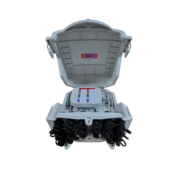
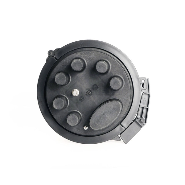
FTTH clamps are specialized devices designed to hold and secure fiber optic strands within an installation. These clamps not only protect the delicate optical cables from damage but also maintain proper alignment, which is vital for signal integrity. “Securing” fiber optic cable goes beyond just preventing it from moving; it encompasses protecting its delicate core from physical stress, environmental degradation, and ensuring long-term signal integrity. Achieving this requires a combination of thoughtful design, appropriate materials, and. OPGW is primarily used by the electric utility industry, placed in the secure topmost position of the transmission line where it “shields” the all-important conductors from lightning while providing a telecommunications path for internal as well as third party communications. With a combination of stainless steel wire and reinforced nylon body, Fibeye tension clamps offer excellent durability and performance. Do you need a reliable, durable, and. Fasclamp is a fiber optic cable clamp that is used to secure the fiber cables and prevent movement while prepping and splicing fiber cables. Designed by a by a fiber splicer with 25 years experience in the field, FasClamp and FasclampXL can be used in any splicing vehicle, trailer, or table mounted. Fiber optic cable clamps are devices used to secure and stabilize fiber optic cables in a wide range of applications, including telecommunications, data centers, and network systems.
[PDF]
In this video, we'll walk you through the process of wiring a home distribution box with a detailed connection diagram. Whether you're an electrician or a DIY enthusiast, this guide will help you understand the basics of home electrical distribution. more Welcome to our channel! In this video. A distribution box is the heart of any electrical system. It takes the incoming power and safely distributes it to different circuits throughout your building. However, the key to. In this article, we'll explain how to install a weatherproof electrical box, from selecting the right materials to properly securing the box in place. Weatherproof electrical boxes are designed to handle extreme weather conditions, such as heavy rain and strong winds. They're also designed to. Whether you're a do-it-yourselfer, the neighborhood handyman, or a professional electrician, knowing how to properly install a weatherproof electrical junction box can save time, and your system components will continueto operate for years. Standard indoor electrical boxes are not designed to handle exposure to rain, snow, or high humidity, which can quickly lead to corrosion. Whether adding a GFCI outlet for safety or upgrading an exterior outlet for weather-resistant durability, it's essential to follow proper electrical wiring guidelines to ensure compliance with local codes and prevent hazards. This guide explains the different types of outdoor electrical boxes.
[PDF]
We have the equipment and personnel for the installation of the cable way system, Our national and international experiences in Costa Rica, México, Senegal, Mozambique, Camerún, Costa de Marfil, Ghana, Puerto Rico, Haití, República dominicana, Guatemala and others, have given. We have the equipment and personnel for the installation of the cable way system, Our national and international experiences in Costa Rica, México, Senegal, Mozambique, Camerún, Costa de Marfil, Ghana, Puerto Rico, Haití, República dominicana, Guatemala and others, have given. Costa Rica Phone — 011-506-2438-1980 Purchasing Email — purchasing@ticoelectronics. com Solicitud de Empleo Para oportunidades de empleo, haga clic aquí. This field is for validation purposes and should be left unchanged. With a $1 billion inventory of the industry's most trusted brands you can meet your quality and lead time demands right here. If you can't find what you're looking for, we're available to help. Costa Rica is the fifth largest Central American country with a population of almost five million. Traditionally, the country's major exports have been agriculture goods, such as coffee, sugar cane, pineapples and bananas; however, since the 1990s, manufacturing has made major in-roads into their.
[PDF]
This video shows real on-site footage of electrical installation, demonstrating safe and standardized wiring methods used by professionals. A distribution board, also known as a DB box, is like the central hub of an electrical system. It contains multiple circuit breakers and connects various electrical circuits to ensure. Box installation: Make sure that Distribution box has been correctly installed and fixed. Material preparation: Prepare the required circuit breakers, wires, wiring ties and other materials, and ensure that they meet the design drawings and installation requirements. It serves as a central hub for distributing electricity throughout a building, ensuring that power is delivered safely and efficiently to all the required locations. It takes the incoming power and safely distributes it to different circuits throughout your building. Whether in a home or an industrial facility, this box keeps your electrical setup organized, functional, and efficient. It has three categories: residential, commercial and industrial electrical distribution boxes, all of which play important roles in their respective electrical.
[PDF]