Trim solid or stranded wire to length and insert into clamp-style terminals. Tighten with a screwdriver. Tug on all connections to make sure they are secure. Close up electrical boxes. Turn on the power and check your work. Learn how to wire a distribution box step by step! This video shows real on-site footage of electrical installation, demonstrating safe and standardized wiring methods used by professionals. Make sure the power's off using a non-contact voltage tester or multimeter. One final tip: Get into the habit of making connections in this. This guide provides step-by-step instructions for connecting a distribution box and highlights key factors to consider during installation. What Is a Distribution Box? A distribution box, also known as an electrical distribution board, is a critical component in electrical systems. It serves as a. Material preparation: Prepare the required circuit breakers, wires, wiring ties and other materials, and ensure that they meet the design drawings and installation requirements. Choose the right box based on environment (indoor/outdoor), load capacity, and durability. Check for proper IP/NEMA ratings and material quality. Beginning of dialog window. Escape will cancel and close the window. This modal can be closed by pressing the Escape key or activating the close button.
[PDF]

Thinner cables can be utilized to connect the control switch to the relay; this saves space, weight, and cost. The same voltage and current ratings as other types of switches, such as mechanical switches, do not limit relays. This handbook covers the code of practice in protection circuitry including standard lead and device numbers, mode of connections at terminal strips, colour codes in multicore cables, dos and donts in execution. Also principles of various protective relays and schemes including special protection. A control relay is an electrically operated switch that enables current to flow through a coil that closes or opens the switch. Relays use a small current to control a larger current, making them ideal for controlling high-power devices such as motors, lights, valves, and sensors. When a relay contact is open, this will switch power ON for a circuit when the coil is activated. You'll connect a low-power control circuit to the relay's coil (terminals 85 and 86), which then flips a switch for a separate, high-power circuit running through the. Electrical protection relay has two type protecton as HT panel protection and LT panel protection. HT panel protection relay. The HT power supply is received from GO switch and distributed to the. The rectangular devices are test connection blocks, used for testing and isolation of instrument transformer circuits. : 4 The first protective relays were electromagnetic.
[PDF]
This guide will provide you with a detailed Cat 6 socket wiring diagram, outlining the necessary steps and components required for a successful installation. If you want to install a classic network socket, you must first strip the Cat. A special stripping tool for data cables is used here – for example, the Stripper No. Use side A to remove the protective jacket. 35, you can shorten the network cable (Cat. 7) a little bit, if required. If you have too much cable left, it will be harder to. Learn how to wire a distribution box step by step! This video shows real on-site footage of electrical installation, demonstrating safe and standardized wiring methods used by professionals. 5mm² wires, and the air conditioning circuit can use 2. Connection method: Each switch takes a wire from the incoming point and connects it to the incoming end of the switch, or uses parallel connection to reduce the difficulty. Learn how to install a distribution box safely and correctly. Covers wiring, placement, standards, and expert tips for a compliant setup. A distribution box is the heart of any electrical system. It takes the incoming power and safely distributes it to different circuits throughout your building. Understanding the wiring diagram of an electrical panel box is essential for electricians and homeowners alike, as it allows them to troubleshoot any electrical issues, carry out repairs, or make additions to the system.
[PDF]
Live (L) Wire Connection: In a distribution box setup, the incoming live wire (also known as phase or hot wire, denoted as L or Line) connects to the line terminal of the circuit breaker. This serves as the primary source of electrical energy from the mains supply. Correct wiring methods for circuit breakers within distribution boxes are fundamental to ensuring electrical safety and compliance with established codes. The distinction between 1P and 2P circuit breakers plays a pivotal role in determining the appropriate protection level for various circuits. And all the switching and protective devices are installed in the distribution box. Single Phase Distribution Box generally consists of Double Pole MCBs, Single Pole MCBs, and RCCBs. The wire neutral is the return line in an electrical system that brings current from the electrical equipment back to the transformer or distribution box, completing the loop closure of the current. Figure 2-3 What wire is neutral? What does the neutral wire do? Although the neutral wire is usually. Live wires carry the power from the source to a switch or appliance. These may be light switches, electrical outlets, or junction boxes for light fixtures. The live wire is always under voltage, meaning it carries the. The main service panel, also known as the breaker box, is the central distribution point for the home's electrical system.
[PDF]
Where single conductor cables comprising each phase, neutral, or grounded conductor of an alternating-current circuit are connected in parallel as permitted in 310. Joining conductors in parallel is like having two or more smaller conductors connected at each end to make one larger conductor. The single input supply (phase and neutral) is connected to this main MCB. When this MCB is turned on all other MCBs will get the power supply. Single-pole MCBs are used for the output loads. The isolator is used to OPEN and CLOSE the lines manually, which is the main switch of the electrical system. The RCCB is a device used. These are usually connected to thick black or red wires, each carrying 120V in a split-phase system. Verify voltage with a multimeter: each line wire should show ~120V to neutral and ~240V across both hot wires. Load terminals, positioned below the line lugs, distribute current to downstream. What's a neutral?The IEEE defines a Neutral as the conductor that has an equal potential difference between it and all other conductors (hot wires). An example of a neutral wire would be the white/gray wire of a single-phase 120/240 volt system or a three-phase 4-wire Wye system, Figure 1-1. 10 (G) (2) through (G) (6).
[PDF]
This comprehensive guide provides step-by-step instructions for sizing electrical cables in accordance with Australian Standard AS/NZS 3008. Electrolytic Tough Pitch (ETP) : The workhorse for most applications - 99. 9% pure with oxygen molecules peppered throughout the structure. Offers optimal balance of conductivity and cost Oxygen-Free Copper (OFC) : Created in oxygen-free environments, eliminating oxide impurities. Has marginally. Selecting the correct cable size is not just about electrical efficiency—it is a critical safety requirement. Under-sized cables lead to insulation failure, fire hazards, and significant equipment damage. Whether you're an electrical engineer, contractor, or student, this resource will help you master the essential calculations for selecting the. The National Electrical Code (NEC) provides clear guidelines for ground wire sizing through Table 250. 122, but understanding how to apply these requirements correctly can make the difference between a safe installation and a costly code violation. Proper grounding conductor sizing is critical for. Professional electrical wire sizing tool based on National Electrical Code (NEC) standards. Calculate proper wire gauge, voltage drop, and ampacity for safe electrical installations. Input your electrical parameters to get accurate wire size.
[PDF]
This post is a step-by-step detailed installation guide on how to run wires for security cameras to help you install security camera wiring for both indoors and outdoors. Proper wiring is crucial to ensuring that your security cameras function effectively and provide clear, uninterrupted footage. How to connect your cameras and recorder to provide power and a video feed, including for remote viewing via smartphones and computers. We always recommend wired systems when possible. We offer two different types of wired security camera systems -. There are two different ways to install security camera wiring: POE security camera wiring and wireless security camera wiring. Whether you're securing your home or business, the quality and installation of your camera wiring play a crucial role in ensuring consistent, high-quality video feeds. In this guide, we. This article provides a detailed principle explanation of 3R methods (reamplification, reshaping, and retiming) to reach the extension of passive optical networks. The second part of the article focuses on optical amplifiers, their advantages and disadvantages, deployment, and principles. We. In this step-by-step guide, we will walk you through the process of wiring your 2 wire security camera, providing you with a clear understanding of the necessary steps and a helpful diagram to refer to.
[PDF]
In this video, we'll walk you through the process of wiring a home distribution box with a detailed connection diagram. Whether you're an electrician or a DIY enthusiast, this guide will help you understand the basics of home electrical distribution. What is Distribution Board? Distribution board. An electrical panel box, also known as a breaker box or a distribution board, is a crucial component of any electrical system. It serves as a central hub for distributing electricity throughout a building, ensuring that power is delivered safely and efficiently to all the required locations. Distribution Board or DB is an electricity supply system or a common enclosure that distributes the electrical power feed into subcircuits. It includes isolator, RCCB (Residual current circuit breaker) or RCD (Residual-current device) devices, protective fuses or MCB's (Miniature Circuit Breaker). A distribution board or distribution box is where the main power supply is distributed to multiple loads. And all the switching and protective devices are installed in the distribution box. Single Phase Distribution Box generally consists of Double Pole MCBs, Single Pole MCBs, and RCCBs. In the following tutorial, we will show how to wire 120V single-phase and 240V split-phase circuit breakers and loads inside a residential main panel. The figure below shows a typical breaker panel used for 120V and 240V circuits. Three conductors enter the main panel from the energy meter and main.
[PDF]
In this video, we'll walk you through the process of wiring a home distribution box with a detailed connection diagram. Whether you're an electrician or a DIY enthusiast, this guide will help you understand the basics of home electrical distribution. more Welcome to our channel! In this video. A distribution board or distribution box is where the main power supply is distributed to multiple loads. And all the switching and protective devices are installed in the distribution box. Single Phase Distribution Box generally consists of Double Pole MCBs, Single Pole MCBs, and RCCBs. Single Phase wiring installation is the most common wiring in residential buildings. It is essential for managing the electrical supply to various appliances and circuits in the building. Its function is to safely divide the incoming high-amperage utility power into smaller, manageable branch circuits that supply power to lights, outlets, and.
[PDF]
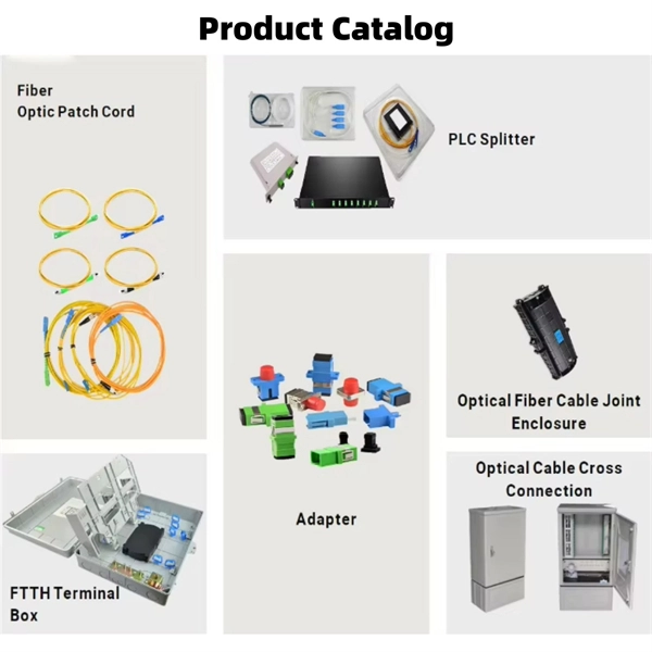
Optical fibre has been installed along 1,600 kilometres length so far under the Optical Fibre Backbone Network Expansion Project across the country. Hording board used for barricading should be prop rly fastened to the ground. Further, to allow movement of commuters, backfilling shall be done as soon as necessary length of pipe are laid in trench for easy and quic completion of the Project. The Contractor shall be. o the Home (FTTH) Infrastructure (September isaster Warning: Opportunities and Legal Challenges (ITU, 2012). Available line for sustainable transport in Asia-Pacific, 6 Dec er nce with support from government authorities and market players. The planning for setting up the infrastructure should. As per the agreement, an extension of optical fibers would complete in two years. So far, the optical fibers have been laid on 1,006-km (46.
[PDF]
Each wire must connect to its appropriate terminal: Live wires (red or brown) connect to the MCB's live terminal. Neutral wires (black or blue) go to the neutral bus bar. Welcome to our channel! In this video, we'll walk you through the process of wiring a home distribution box with a detailed connection diagram. Whether you're an electrician or a DIY enthusiast, this guide will. This guide provides step-by-step instructions for connecting a distribution box and highlights key factors to consider during installation. What Is a Distribution Box? A distribution box, also known as an electrical distribution board, is a critical component in electrical systems. In Single Phase supply (230V in UK, EU and 120V & 240V in the US & Canada), there are two (one is Line (aka Phase, Hot or Live) and the other one is Neutral) incoming cables from the utility poles to the kWh energy. A distribution board or distribution box is where the main power supply is distributed to multiple loads. And all the switching and protective devices are installed in the distribution box. Single Phase Distribution Box generally consists of Double Pole MCBs, Single Pole MCBs, and RCCBs.
[PDF]
The primary function of a feeder wire is to facilitate bulk power transfer from a central source to a subpanel or a secondary distribution center. An example is the large cable running from the main service panel to a subpanel in a detached garage, basement, or workshop. A main panel and a sub-panel are both important components of an electrical distribution system. It is usually located where the main electrical service enters the building, often on an. Main feeder wires are the arteries of a building's electrical system, designed to safely and efficiently transport a large volume of power from the service entrance to secondary distribution points. They form the backbone of the electrical distribution network, handling the substantial current. An electrical sub panel, also known as a sub distribution board or sub circuit breaker panel, is a smaller secondary panel connected to the main electrical panel in a building. It serves as an extension of the main electrical panel to distribute power to different areas or circuits within a. Distribution board is a safe system designed for house or building that included protective devices, isolator switches, circuit breaker and fuses to safely connect the cables and wires to the sub circuits and final sub circuits including their associated Live (Phase) Neutral and Earth conductors. The distribution box acts as the center of power distribution, distributing electricity to all connected devices.
[PDF]
Classes 1, 2, 3, and 4, communications, fire alarm, and optical fiber cables are all addressed in the NEC. Several changes related to communications cables have received the green light to be included in the 2023 National Electrical Code. Nuclear Regulatory Commission (NRC) is issuing for public comment a draft Regulatory Guide (DG), DG-1427, “Qualification of Fiber-Optic Cables, Connections, and Optical Fiber Splices for Use in Safety Systems for Production and Utilization Facilities. ” DG-1427 is newly proposed Revision 0. The following links on this page are to Adobe Portable Document Format (PDF) files. To obtain a free viewer for displaying this format, see our Plugins, Viewers, and Other Tools. ms for Production and Utilization Facilities. By Stanley Kaufman, PhD, CableSafe Inc. and Ronald Tellas. This part provides guidance to Federal agencies on the implementation of the Buy America Preference applicable to Federal financial assistance set forth in part I of subtitle A, Buy America Sourcing Preferences, of the Build America, Buy America Act included in the Infrastructure Investment and.
[PDF]
This video shows real on-site footage of electrical installation, demonstrating safe and standardized wiring methods used by professionals. more Learn how to wire a distribution box step by step! This video shows real on-site footage of. Hey, in this article we are going to see the Single Phase Distribution Box Wiring Diagram and Connection Procedure. A distribution board or distribution box is where the main power supply is distributed to multiple loads. And all the switching and protective devices are installed in the. Box installation: Make sure that Distribution box has been correctly installed and fixed. Material preparation: Prepare the required circuit breakers, wires, wiring ties and other materials, and ensure that they meet the design drawings and installation requirements. Location determination:. In this video, we'll walk you through the process of wiring a home distribution box with a detailed connection diagram. Whether you're an electrician or a DIY enthusiast, this guide will help you understand the basics of home electrical distribution. What Is a Distribution Box? A distribution box, also known as an electrical distribution board, is a critical component in electrical systems. It serves as a.
[PDF]
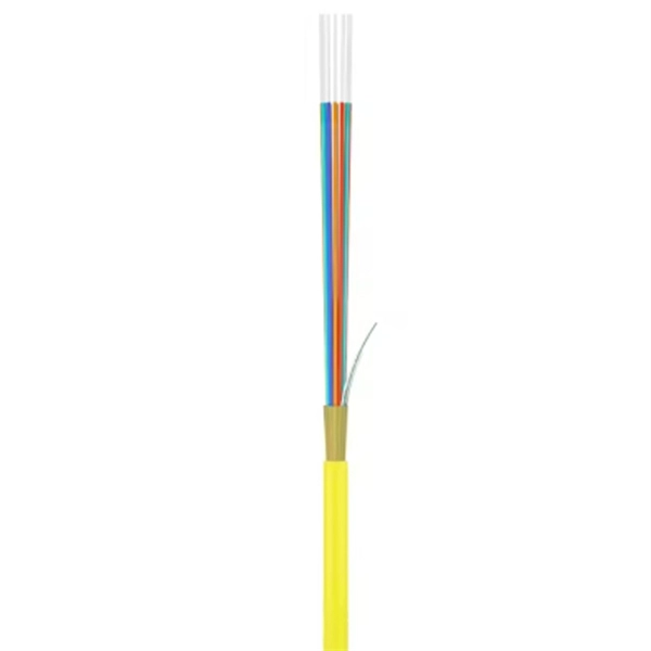
Glass fiber and plastic fiber is fragile. When individual fibers break, light transmission and uniformity are reduced. After the first few fibers break at a stress point, a chain reaction occurs, hastening t.
[PDF]