Trim solid or stranded wire to length and insert into clamp-style terminals. Tighten with a screwdriver. Tug on all connections to make sure they are secure. Close up electrical boxes. Turn on the power and check your work. Learn how to wire a distribution box step by step! This video shows real on-site footage of electrical installation, demonstrating safe and standardized wiring methods used by professionals. Make sure the power's off using a non-contact voltage tester or multimeter. One final tip: Get into the habit of making connections in this. This guide provides step-by-step instructions for connecting a distribution box and highlights key factors to consider during installation. What Is a Distribution Box? A distribution box, also known as an electrical distribution board, is a critical component in electrical systems. It serves as a. Material preparation: Prepare the required circuit breakers, wires, wiring ties and other materials, and ensure that they meet the design drawings and installation requirements. Choose the right box based on environment (indoor/outdoor), load capacity, and durability. Check for proper IP/NEMA ratings and material quality. Beginning of dialog window. Escape will cancel and close the window. This modal can be closed by pressing the Escape key or activating the close button.
[PDF]
Follow a clear step-by-step process: install the ground rod deeply, connect the grounding wire securely, attach it to the panel's ground bus bar, and test the system with proper equipment. Installed correctly, grounding wire can prevent electrical shocks or fires at homes or in offices. This guide reviews the basics of electrical grounding, how to safely ground wiring and how to check if wire is grounded. SHOP GROUNDING WIRES NOW Why Does Wiring Need to be Grounded? Install grounding. However, for experienced DIYers, this guide provides a detailed, step-by-step approach to ensuring your circuit breaker box is properly grounded, enhancing electrical safety grounding throughout your home. It. Section 250. For grounded systems, the NEC requires you to perform all of the following: electrical system grounding, electrical equipment grounding, electrical equipment. Drive a ground rod into the earth and attach a grounding wire to the main electrical panel to add grounding to an existing panel. Install new outlets with a continuous grounding connection to the grounding rod. In this post, I'll go through why every electrical panel should be grounded, what ground. The correct connection method of Distribution box grounding wire mainly includes the following steps: 1. Find the grounding bar or PE bar Open the distribution box and find the position marked with the grounding plate or PE letter.
[PDF]
In this video, we'll walk you through the process of wiring a home distribution box with a detailed connection diagram. Whether you're an electrician or a DIY enthusiast, this guide will help you understand the basics of home electrical distribution. more Welcome to our channel! In this video. Understanding the wiring diagram of an electrical panel box is essential for electricians and homeowners alike, as it allows them to troubleshoot any electrical issues, carry out repairs, or make additions to the system. The electrical panel box wiring diagram provides a visual representation of. A distribution board or distribution box is where the main power supply is distributed to multiple loads. And all the switching and protective devices are installed in the distribution box. Single Phase Distribution Box generally consists of Double Pole MCBs, Single Pole MCBs, and RCCBs. Connect the two hot conductors (typically black and red) to the line terminals of the main disconnect switch. Tighten each lug to 250 inch-pounds using a torque wrench. What is Distribution Board? Distribution board.
[PDF]
This guide will provide you with a detailed Cat 6 socket wiring diagram, outlining the necessary steps and components required for a successful installation. If you want to install a classic network socket, you must first strip the Cat. A special stripping tool for data cables is used here – for example, the Stripper No. Use side A to remove the protective jacket. 35, you can shorten the network cable (Cat. 7) a little bit, if required. If you have too much cable left, it will be harder to. Learn how to wire a distribution box step by step! This video shows real on-site footage of electrical installation, demonstrating safe and standardized wiring methods used by professionals. 5mm² wires, and the air conditioning circuit can use 2. Connection method: Each switch takes a wire from the incoming point and connects it to the incoming end of the switch, or uses parallel connection to reduce the difficulty. Learn how to install a distribution box safely and correctly. Covers wiring, placement, standards, and expert tips for a compliant setup. A distribution box is the heart of any electrical system. It takes the incoming power and safely distributes it to different circuits throughout your building. Understanding the wiring diagram of an electrical panel box is essential for electricians and homeowners alike, as it allows them to troubleshoot any electrical issues, carry out repairs, or make additions to the system.
[PDF]
Each wire must connect to its appropriate terminal: Live wires (red or brown) connect to the MCB's live terminal. Neutral wires (black or blue) go to the neutral bus bar. Welcome to our channel! In this video, we'll walk you through the process of wiring a home distribution box with a detailed connection diagram. Whether you're an electrician or a DIY enthusiast, this guide will. This guide provides step-by-step instructions for connecting a distribution box and highlights key factors to consider during installation. What Is a Distribution Box? A distribution box, also known as an electrical distribution board, is a critical component in electrical systems. In Single Phase supply (230V in UK, EU and 120V & 240V in the US & Canada), there are two (one is Line (aka Phase, Hot or Live) and the other one is Neutral) incoming cables from the utility poles to the kWh energy. A distribution board or distribution box is where the main power supply is distributed to multiple loads. And all the switching and protective devices are installed in the distribution box. Single Phase Distribution Box generally consists of Double Pole MCBs, Single Pole MCBs, and RCCBs.
[PDF]
On the US market, a 5. 26 mm 2 (10 AWG) ground wire must be used, and in all other markets a 6 mm 2 must be used. Grounding of the units: Attach a ground wire from one of the threaded studs (A) at the bottom of the housing, to the mounting plate (B). Attach a second grounding wire from the mounting. The correct connection method of Distribution box grounding wire mainly includes the following steps: 1. Find the grounding bar or PE bar Open the distribution box and find the position marked with the grounding plate or PE letter. The basic rule achieves this through an equipment grounding jumper; four exceptions. An equipment grounding conductor passing through the box without a splice is not required to be joined inside the box to others that are spliced in the box. 148 addresses the continuity of equipment grounding conductors and their attachment in boxes. Not all boxes are metal or provide. Correct grounding of services depends upon understanding the definition and role of the grounded conductor. The neutral conductor is typically the grounded conductor connected to the system's neutral point, carrying current under normal operation. Whether you're a seasoned pro or just starting out, this comprehensive guide will give you practical.
[PDF]
Where single conductor cables comprising each phase, neutral, or grounded conductor of an alternating-current circuit are connected in parallel as permitted in 310. Joining conductors in parallel is like having two or more smaller conductors connected at each end to make one larger conductor. The single input supply (phase and neutral) is connected to this main MCB. When this MCB is turned on all other MCBs will get the power supply. Single-pole MCBs are used for the output loads. The isolator is used to OPEN and CLOSE the lines manually, which is the main switch of the electrical system. The RCCB is a device used. These are usually connected to thick black or red wires, each carrying 120V in a split-phase system. Verify voltage with a multimeter: each line wire should show ~120V to neutral and ~240V across both hot wires. Load terminals, positioned below the line lugs, distribute current to downstream. What's a neutral?The IEEE defines a Neutral as the conductor that has an equal potential difference between it and all other conductors (hot wires). An example of a neutral wire would be the white/gray wire of a single-phase 120/240 volt system or a three-phase 4-wire Wye system, Figure 1-1. 10 (G) (2) through (G) (6).
[PDF]
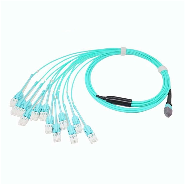
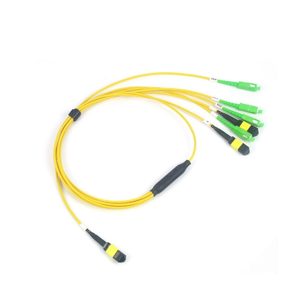
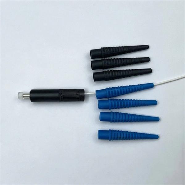
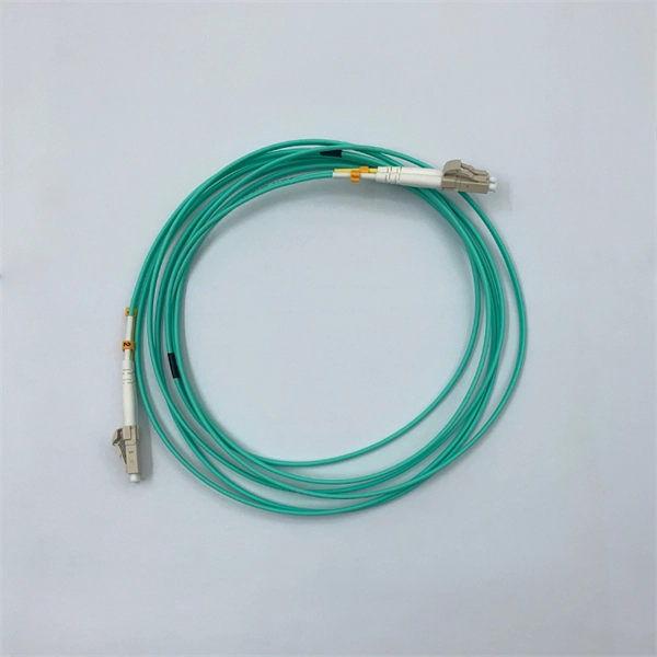
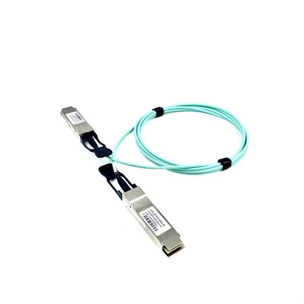
Fiber optic patch cables are ideal for supporting high speed telecommunication network fiber applications. They are manufactured and tested in compliance with TIA 604 (FOCIS), IEC 61754 and YD/T industry s.
[PDF]
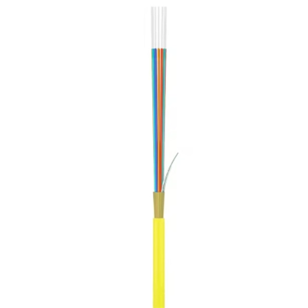
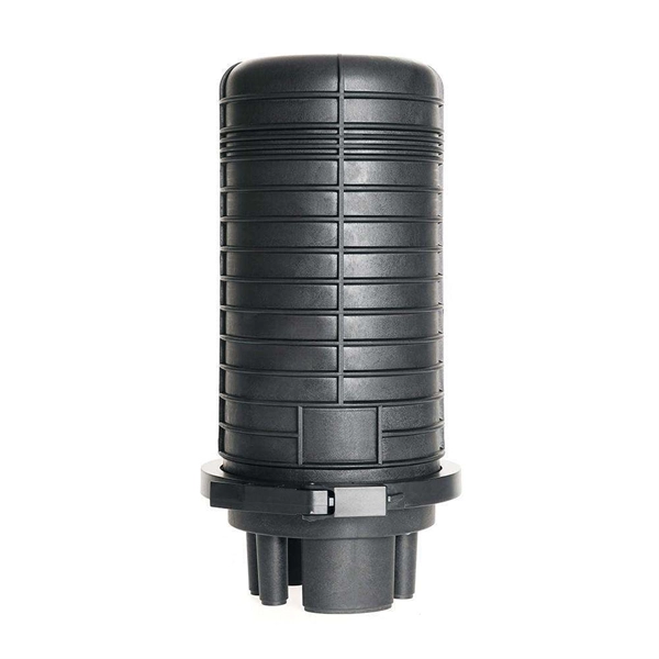
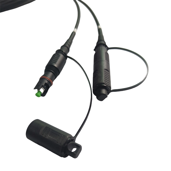
Stranded fiber optic cable is a loose tube made of high-modulus plastic by adding colored optical fiber and ointment at the same time, and the optical fiber can move in the tube. Different loose tubes are twisted along the central reinforcing core to make the cable core. A TOSLINK optical fiber cable with a clear jacket. These cables are used mainly for digital audio connections between devices. The cable core is added. A steel messenger is a stranded steel cable that acts lashing wire. This document describes further details of messenger strand, lashing wire, and the planning and installation process. Steel messenger strand consists. Fiber optic cables are used to transmit data and audio signals using light. They come in different types, each designed for specific applications and distances. This guide will help you identify the most common types of fiber optic cables and understand how many strands of fiber are typically found. Unlike copper wires, which are limited by lower data transmission speeds, shorter transmission distances, and higher susceptibility to electromagnetic interference, fiber optic cables offer unparalleled performance and can cover much greater distances without bumping up against signal degradation. Fiber optic "cable" refers to the complete assembly of fibers, other internal parts like buffer tubes, ripcords, stiffeners, strength members all included inside an outer protective covering called the jacket.
[PDF]
The primary function of a feeder wire is to facilitate bulk power transfer from a central source to a subpanel or a secondary distribution center. An example is the large cable running from the main service panel to a subpanel in a detached garage, basement, or workshop. A main panel and a sub-panel are both important components of an electrical distribution system. It is usually located where the main electrical service enters the building, often on an. Main feeder wires are the arteries of a building's electrical system, designed to safely and efficiently transport a large volume of power from the service entrance to secondary distribution points. They form the backbone of the electrical distribution network, handling the substantial current. An electrical sub panel, also known as a sub distribution board or sub circuit breaker panel, is a smaller secondary panel connected to the main electrical panel in a building. It serves as an extension of the main electrical panel to distribute power to different areas or circuits within a. Distribution board is a safe system designed for house or building that included protective devices, isolator switches, circuit breaker and fuses to safely connect the cables and wires to the sub circuits and final sub circuits including their associated Live (Phase) Neutral and Earth conductors. The distribution box acts as the center of power distribution, distributing electricity to all connected devices.
[PDF]
Glass fiber and plastic fiber is fragile. When individual fibers break, light transmission and uniformity are reduced. After the first few fibers break at a stress point, a chain reaction occurs, hastening t.
[PDF]
Practice good wiring: secure grounding, neat cable management, proper insulation, and correct wire gauge and breaker size. Include protection devices like breakers, fuses, and surge protectors—each circuit should have its own protection. Comply with standards: Follow NEC, IEC . We'll show you how to run the wires, install the proper jacks and hook up the central distribution box. The new system doesn't mean you have to scrap your old cables and jacks. Existing phone lines and jacks can coexist with your new communication wiring system. We recommend that you initially. Learn how to wire a distribution box step by step! This video shows real on-site footage of electrical installation, demonstrating safe and standardized wiring methods used by professionals. And all the switching and protective devices are installed in the distribution box. Single Phase Distribution Box generally consists of Double Pole MCBs, Single Pole MCBs, and RCCBs. It is usually equipped with circuit breakers, fuses, terminal connectors, and other components. It is mainly used to isolate fault circuits, prevent overload, and ensure the safe operation of. Material preparation: Prepare the required circuit breakers, wires, wiring ties and other materials, and ensure that they meet the design drawings and installation requirements. Location determination: Determine the installation position of the circuit breaker according to the position of the.
[PDF]
We have the equipment and personnel for the installation of the cable way system, Our national and international experiences in Costa Rica, México, Senegal, Mozambique, Camerún, Costa de Marfil, Ghana, Puerto Rico, Haití, República dominicana, Guatemala and others, have given. We have the equipment and personnel for the installation of the cable way system, Our national and international experiences in Costa Rica, México, Senegal, Mozambique, Camerún, Costa de Marfil, Ghana, Puerto Rico, Haití, República dominicana, Guatemala and others, have given. Costa Rica Phone — 011-506-2438-1980 Purchasing Email — purchasing@ticoelectronics. com Solicitud de Empleo Para oportunidades de empleo, haga clic aquí. This field is for validation purposes and should be left unchanged. With a $1 billion inventory of the industry's most trusted brands you can meet your quality and lead time demands right here. If you can't find what you're looking for, we're available to help. Costa Rica is the fifth largest Central American country with a population of almost five million. Traditionally, the country's major exports have been agriculture goods, such as coffee, sugar cane, pineapples and bananas; however, since the 1990s, manufacturing has made major in-roads into their.
[PDF]
This video shows real on-site footage of electrical installation, demonstrating safe and standardized wiring methods used by professionals. A distribution board, also known as a DB box, is like the central hub of an electrical system. It contains multiple circuit breakers and connects various electrical circuits to ensure. Box installation: Make sure that Distribution box has been correctly installed and fixed. Material preparation: Prepare the required circuit breakers, wires, wiring ties and other materials, and ensure that they meet the design drawings and installation requirements. It serves as a central hub for distributing electricity throughout a building, ensuring that power is delivered safely and efficiently to all the required locations. It takes the incoming power and safely distributes it to different circuits throughout your building. Whether in a home or an industrial facility, this box keeps your electrical setup organized, functional, and efficient. It has three categories: residential, commercial and industrial electrical distribution boxes, all of which play important roles in their respective electrical.
[PDF]
ShowMeCables offers a wide selection of LMR-600® thick low loss cables for long-distance runs. These LMR-600 cables are designed with flexibility, low loss and RF shielding with options such as ultra-flex, weatherproof and fire retardant rating for safe indoor, outdoor, or direct. TC-240-FM-X 3190-2891 <1. N Male Straight Plug 3. 35:1 (6) Hex/Knurl Solder Crimp A/G 1. Since 1975 delivering the world the best copper and copper alloy products to build a more connected, clean and efficient planet. is a Peruvian manufacturer that specializes in the design and production of electrical cables and conductors made from copper and aluminum for low and medium voltage applications. These. Check each product page for other buying options. Alligator Clips Electrical with Wires UL1015/18AWG, 6 Colors Jumper Test Leads Set, 1. Clips Soldered with Wires- EDGELEC Need help?. Our wire and cables have been helping real, hardworking pros on the job for more than 45 years. Their success is our success. Direct Wire is widely known as the market leader for highly durable and versatile cables and assemblies manufactured to stringent U. and international standards.
[PDF]