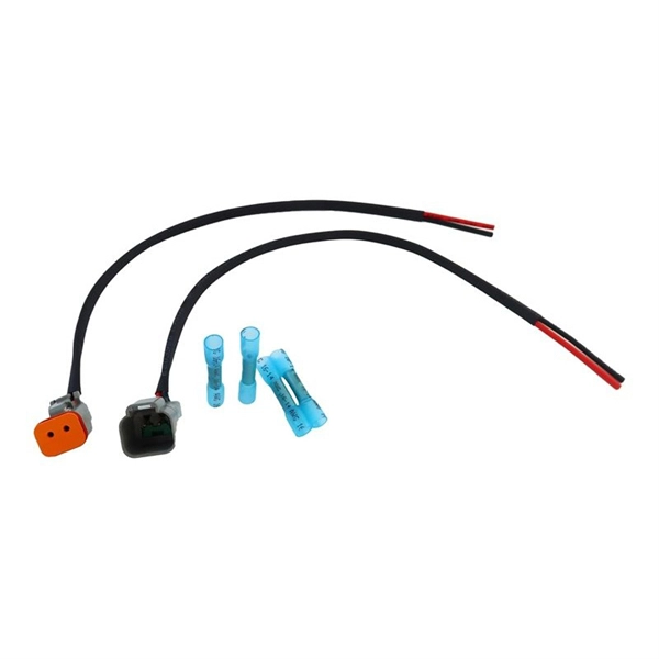
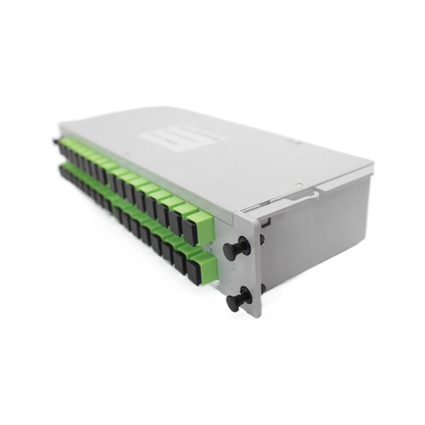
Rack Elevation or Server Rack Layout Software are simple tools to plan and document the cabling of your server cabinet. To make it even easier for you, we launched the free online Rack Planner. It helps you create a helpful rack diagram and keep your network tidy. Network cabinet cabling describes the structured connection and arrangement of all IT components in a server rack. The aim is a secure, maintainable and scalable operation of the network environment. Step-by-step guide: In this way, patch panels, switches, cable routing and documentation are. Creating a rack diagram is an important step to having sustainable good cable management in the network cabinet. Let's take a look at the essential components, selection criteria, and best practices for efficiency, order and protection of the network. Use cabinet screws to fix the network patch panel to the network cabinet. Note the wiring sequence on the patch panel when wiring, as T568A and T568B have different sequences. Wiring a server or network rack feels simple at first. Cables plug in, and devices turn on. Then problems appear. Slow speeds and tangled wires with card troubleshooting. Clean wiring prevents those issues before they start.
[PDF]
In this step-by-step tutorial, we'll cover: ✅ Tools you need ✅ Safety precautions ✅ Mounting the box ✅ Wiring tips ✅ Final checks Perfect for beginners, DIYers, and electricians who want a clear installation guide. more Learn how to properly install an electrical. Electrical switch box wiring is a critical aspect of any electrical installation. The electrical panel box wiring diagram provides a visual representation of. A junction box provides a code-approved place to house wire connections, whether for outlets, switches, or splices. Here's how to install one. We may be compensated if you purchase through links on our website. It acts as a central connection point for various electrical wires, allowing for the easy distribution of electricity to different fixtures and devices. A properly installed and wired junction box ensures the safety and. Are you ready to master the skill of building electrical panels? This detailed guide provides an excellent base for beginners. Learn about the essential components of panels, such as the circuit breakers and fuses that safeguard against hazards. Then, delve into complex wiring configurations.
[PDF]

In this guide, we will explore the significance of connecting PVC conduit to electrical boxes and provide you with a step-by-step process to accomplish this task effectively. Whether you're dealing with rigid metal conduit (RMC), PVC, or flexible conduit that's already in place, it can be removed or replaced, but there's no magic wand. You'll need to consider the type of conduit, the installation method, and. Electrical conduit fittings form the outer covering for most electrical wiring from one point to the next. They shield the wires from the external environment so as to make the wire last longer and also to keep humans and pets safe from electric shocks or other such vulnerabilities. The breaker box, or service panel, serves as the central distribution point, housing the circuit breakers that protect individual circuits from overcurrent conditions. Connecting made easy: How to effortlessly connect PVC conduit to electrical boxes! Installing electrical systems just got simpler with Ledes' seamless conduit connections! 💡. Firstly, it. Why Publish? How to Repair and Remove Conduit for Electric Wires: Let me teach you how to easily repair and remove conduit for electric wires. For the full guide and more tips read the post in 123 Do It Yourself blog: com/2014/01/22/22/.
[PDF]
Simple 3-phase distribution board wiring diagram for home use, showing safe connection of power supply, breakers, neutral, and earth for residential electrical systems. Hey, in this article we are going to see the Three (3) Phase Distribution Board Wiring Diagram and Connection Procedure. The three-phase distribution board is used to distribute power to the three-phase loads and circuits such as three-phase motors, three-phase machinery, three-phase to. In a newly constructed residential area, a 10kV power line is introduced into the substation. After stepping down the voltage through the transformer's low-voltage side (0. The following is a detailed introduction about it: - **First-level Distribution. Utilities may have some control over and access to the energy stored in electric vehicles attached to the grid. ndards and conformity assessment activities in the United States. ANSI facilitates and promotes voluntary consensus standar rty or economic loss due to fire, electrical and related hazards. They deliver information and knowledge through more than 300 consensus codes and nspection to protect people.
[PDF]
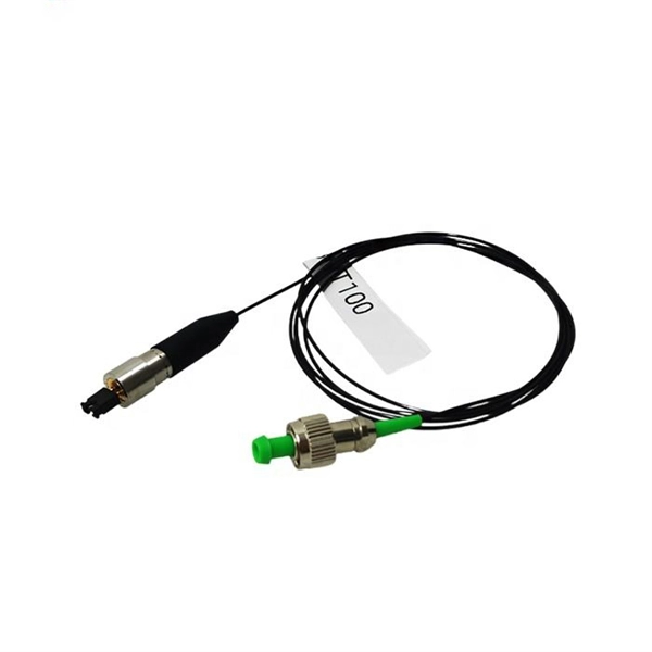
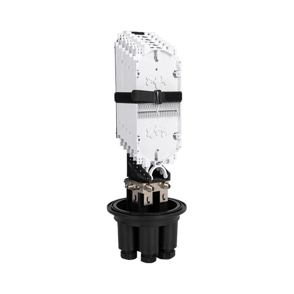
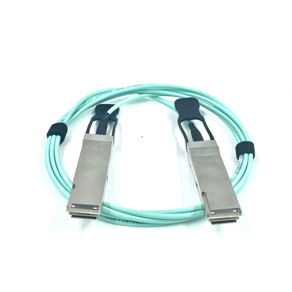
This diagram highlights media converters, switches, and cable types. Also thanks to Init7 (for the great service), r/FiberOptics and FS for providing me with what I needed to get this setup going. If you find this article useful and you are considering Init7 as your provider you can use my referral code “20700408098” to get CHF 111. - off hardware and also support me. Keeping this page as a placeholder for now. Have any questions? Talk with us directly using LiveChat. A fiber optics network diagram illustrates how high-speed data travels from an internet service provider to end users. By using light signals, fiber optics provide faster speeds and better reliability than. MS Visio has long been the default choice for drafting fiber network diagrams, and with the right stencil libraries it can be used to draw everything from backbone routes to detailed patch panel layouts. When fiber techs look for visio fiber stencils, they are usually solving a very practical. Be among the first to receive important product updates, insights and news. Fiber optic cable is used for everything from demarcation point wiring to network signal distribution to video signal extension. Often, fiber enters the structure to a centralized rack or data room where it is connected to a modem. The modem connects to a network switch which connects each remote.
[PDF]

One-line diagrams and detailed network data (lines, transformers, buses). Short-circuit models, including fault current calculations under various system configurations. Protective relay settings and coordination curves. Historical. presentation of protection and control relaying. The report will identify methodology behind these practices, present issues raised by the integration of microprocessor relays and the internal logic and external communication configurations, ying. Schematic diagrams of protection relays are essential tools for power engineers in the power generation, transmission, and distribution industry. This includes AC schematics and DC schematics and diagrams that prominently feature relaying. There are other equally important types of drawings that are not the subject. Power System Protective Relays: Principles & Practices Presenter: Rasheek Rifaat, P. Eng, IEEE Life Fellow IEEE/IAS/I&CPSD Protection & Coordination WG Chair Jacobs Canada, Calgary, AB rasheek. com IEEE Southern Alberta Section PES/IAS Joint Chapter Technical Seminar - November 2016. Recognized under 2(f) and 12 (B) of UGC ACT 1956 (Affiliated to JNTUH, Hyderabad, Approved by AICTE - Accredited by NBA & NAAC – 'A' Grade - ISO 9001:2015 Certified) Maisammaguda, Dhulapally (Post Via. Kompally), Secunderabad – 500100, Telangana State, India To introduce all kinds of circuit.
[PDF]
This guide highlights five top-rated options, detailing their tech specs, durability, and ease of use. Each entry provides a quick overview so you can compare sizing, IP ratings, and mounting features before choosing. Limitations of “Dumb” Waterproof Boxes + “Smart” Indoor Switches: Many attempt to achieve outdoor automation by placing an indoor smart switch inside a generic waterproof outdoor electrical box. This creates several problems: —Signal Degradation: The metal or thick plastic of the outdoor box can. We specialize in creating custom NEMA enclosures tailored to your exact needs. Browse our durable lineup of outdoor electrical enclosures designed to protect sensitive components from rain, dust, UV exposure, and harsh environmental conditions. Built for rugged reliability, these enclosures are. Exterior electrical boxes are weatherproof enclosures that protect outdoor electrical connections from moisture, dust, and impact damage. Here's what you need to know: Key Features to Look For: Top Applications: Whether you're adding a new outdoor outlet for holiday lights or upgrading an existing. Discover the 5 best outdoor electrical junction boxes for weatherproof protection. Compare features, materials, and ratings to ensure safe, code-compliant installations. When you're running electrical wiring outdoors, proper protection isn't optional—it's essential for safety and code compliance. Each option balances.
[PDF]
The British Standard Wire Gauge, often referred to as the Standard Wire Gauge or simply SWG, is a unit used to denote (size) as defined by 3737:1964, a standard that has since been withdrawn. It is also known as the Imperial Wire Gauge or British Standard Gauge. Although its use has significantly declined, SWG sizes are still used for measuring the thickness of guitar strings and certain types of electrical.
[PDF]
This video shows real on-site footage of electrical installation, demonstrating safe and standardized wiring methods used by professionals. more Learn how to wire a distribution box step by step!. A distribution box, also known as a distribution board, electrical panel, or breaker box, is an enclosure that houses electrical components responsible for distributing electricity throughout a building. more Learn how to wire a distribution box step by step! This video shows real on-site footage of. In this video, we'll walk you through the process of wiring a home distribution box with a detailed connection diagram. Whether you're an electrician or a DIY enthusiast, this guide will help you understand the basics of home electrical distribution. What is Distribution Board? Distribution board. Connection method: Each switch takes a wire from the incoming point and connects it to the incoming end of the switch, or uses parallel connection to reduce the difficulty of wiring. Wiring Direction: Wiring between the main circuit breaker and each branch circuit breaker in the box generally. Understanding the wiring diagram of an electrical panel box is essential for electricians and homeowners alike, as it allows them to troubleshoot any electrical issues, carry out repairs, or make additions to the system. It takes the incoming power and safely distributes it to different circuits throughout your building. However, the key to.
[PDF]
In this video, we'll walk you through the process of wiring a home distribution box with a detailed connection diagram. Whether you're an electrician or a DIY enthusiast, this guide will help you understand the basics of home electrical distribution. more Welcome to our channel! In this video. A distribution board or distribution box is where the main power supply is distributed to multiple loads. And all the switching and protective devices are installed in the distribution box. Single Phase Distribution Box generally consists of Double Pole MCBs, Single Pole MCBs, and RCCBs. Once the box is securely in place, it's time to bring in the cables that will carry current from the main panel. Beginning of dialog window. Escape will cancel and close the window. This modal can be closed by pressing the Escape key or activating the close button. It takes the incoming power and safely distributes it to different circuits throughout your building. However, the key to. There is a 10-2 (w/ground) UF cable which runs from my main panel in the basement, through the joists in the crawlspace, and exits the house here: Here's the outdoors side, where it connects to the disconnect (which is right out of view at the top of the picture): It doesn't look like whoever did.
[PDF]
Welcome to our channel! In this video, we'll walk you through the process of wiring a home distribution box with a detailed connection diagram. more Welcome to our. A distribution box is the heart of any electrical system. It takes the incoming power and safely distributes it to different circuits throughout your building. Whether in a home or an industrial facility, this box keeps your electrical setup organized, functional, and efficient. It serves as a central hub for distributing electricity throughout a building, ensuring that power is delivered safely and efficiently to all the required locations. The customer is responsible for obtaining permits and inspections, providing and maintaining the overhead path or underground trench and conduit for the power company's wires, and for installing the equipment at the service entrance. The Utility's Rate Schedules, except as provided for in items (A). Distribution Board or DB is an electricity supply system or a common enclosure that distributes the electrical power feed into subcircuits. It includes isolator, RCCB (Residual current circuit breaker) or RCD (Residual-current device) devices, protective fuses or MCB's (Miniature Circuit Breaker).
[PDF]
While there are situations when you will have to route cable through structural members such as studs, joists, and rafters, the job is much easier if you can run the cable along the surfaces of these frames. When you have a situation where you need to run cable through. Running new wiring within existing, finished walls of a wood-framed structure is a common necessity for home upgrades, whether for installing low-voltage data and audio cables or for extending line-voltage electrical circuits. Another is to conceal the cords and cables within the walls. This guide will help you learn how to run low voltage cables through the wall using low voltage boxes and face plates. To learn how to add. Many home improvement projects require you to install new electrical cables inside finished walls. The process is often called "snaking" or "fishing," with good reason. Cables often must be bent, slithered and coaxed around stud spaces and through small holes in the framing. Click on any image to see a larger version. When installing an electrical box, drill a hole in the floor between the studs on the same side as the electrical box. Staple down the wire right above the hole and. Method One: In order to cut the panel correctly, you first need to make the right measurements. Mark this distance on the panel you will be using. Make sure to mark this from the top.
[PDF]
This video shows real on-site footage of electrical installation, demonstrating safe and standardized wiring methods used by professionals. Description: The BSL is illustrated in a low-voltage distribution panel wiring diagram. It consists of three main components: the voltage measuring circuit, secondary circuit protection, and the energy metering circuit. (1) The voltage measurement circuit uses a voltage conversion switch SA and. Primary distribution systems consist of feeders that deliver power from distribution substations to distribution transformers. A feeder usually begins with a feeder breaker at the distribution substation. Many feeders leave substation in a concrete ducts and are routed to a nearby pole. At this. Explosion-proof distribution boxes, vital terminal distribution equipment in power systems, play a crucial role in controlling and protecting industrial electricity in hazardous environments. Given their ubiquity, let's delve into the installation and wiring of indoor distribution boxes today. more Learn how to wire a distribution box step by step! This video shows real on-site footage of. Connection method: Each switch takes a wire from the incoming point and connects it to the incoming end of the switch, or uses parallel connection to reduce the difficulty of wiring. Wiring Direction: Wiring between the main circuit breaker and each branch circuit breaker in the box generally.
[PDF]
Check for proper IP/NEMA ratings and material quality. Ensure safe placement: install in dry, accessible areas with good ventilation and at appropriate height (typically ~1. Practice good wiring: secure grounding, neat cable management, proper insulation, and correct wire gauge. In this guide, we'll break down everything you need to know to install a distribution box correctly and confidently. Choose the right box based on environment (indoor/outdoor), load capacity, and durability. It is usually equipped with circuit breakers, fuses, terminal connectors, and other components. It is mainly used to isolate fault circuits, prevent overload, and ensure the safe operation of. Learn how to wire a distribution box step by step! This video shows real on-site footage of electrical installation, demonstrating safe and standardized wiring methods used by professionals. Follow this guide for a clear and safe connection process: Before starting, always ensure the main power is turned off to avoid electrical shock. It serves as a central hub for distributing electricity throughout a building, ensuring that power is delivered safely and efficiently to all the required locations. Mark and Drill: Confirm the installation place (the method is above) and mark on the wall or installation surface with a marking pen. Distribution Box Installation: Put the distribution box on the.
[PDF]
Take the appropriate rating of MCB and RCCB as per your load requirements. Identify the Input and Output sides of the MCBs and RCCBs. Connect the output of the Main MCB to the input. Primary distribution systems consist of feeders that deliver power from distribution substations to distribution transformers. A feeder usually begins with a feeder breaker at the distribution substation. Many feeders leave substation in a concrete ducts and are routed to a nearby pole. At this. Connection method: Each switch takes a wire from the incoming point and connects it to the incoming end of the switch, or uses parallel connection to reduce the difficulty of wiring. Wiring Direction: Wiring between the main circuit breaker and each branch circuit breaker in the box generally. Correct wiring methods for circuit breakers within distribution boxes are fundamental to ensuring electrical safety and compliance with established codes. The distinction between 1P and 2P circuit breakers plays a pivotal role in determining the appropriate protection level for various circuits. A primary distribution substation is the connection point of a distribution system to a trans-mission or a sub-transmission network. This guide shows you how to organize circuit breaker wiring properly. You will learn to build a safe, efficient, and professional electrical system today. Circuit breaker wiring configurations involve organizing main switches, busbars.
[PDF]