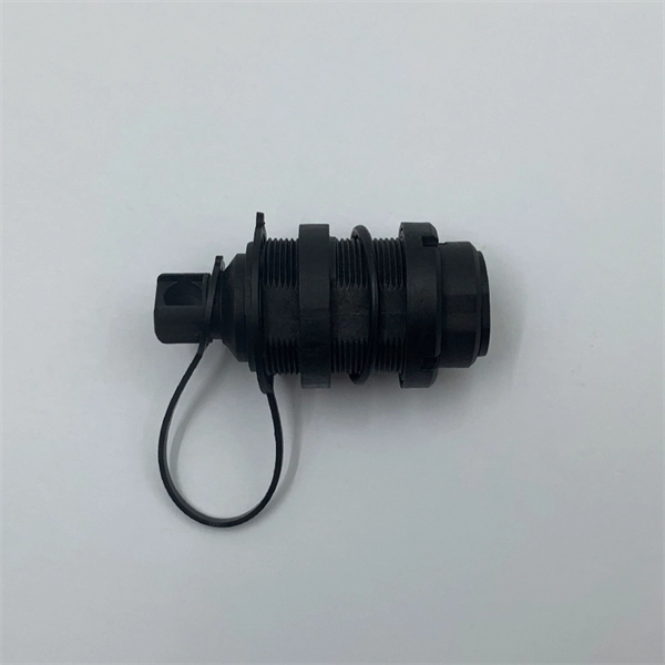
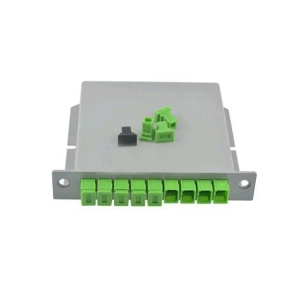
The fiber optic adapter is also called a flange or fiber optic connector. It is usually assembled on various adapter panels and chassis. The Fiber Optic Flange, also known as a Fiber Optic Adapter or Fiber Optic Coupler in engineering, is one of the most fundamental and essential passive devices in fiber optic communication systems. Simply put, it acts like a transition socket or connector adapter in electrical circuits. Important optical fiber connection. Fiber optic adapters are often treated as simple passive interfaces, but their mechanical interaction with the mounting panel plays a critical role in long-term alignment stability and service reliability. The distinction between flanged and flangeless adapters is purely mechanical. It does not. What is a fiber optic connector? The function of fiber optic connectors is to align and connect two or more fibers together to provide a means for attaching to, or decoupling from, a transmitter, receiver, or any other fiber optic component. Most fiber optic connectors are composed of. An optical fiber flange is a type of optical fiber connector used to attach optical fiber cables to other equipment, such as patch panels or network switches. It is designed to provide a secure and reliable connection between optical fibers, minimizing signal loss and ensuring high-quality.
[PDF]
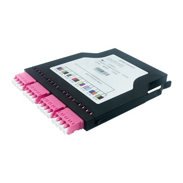
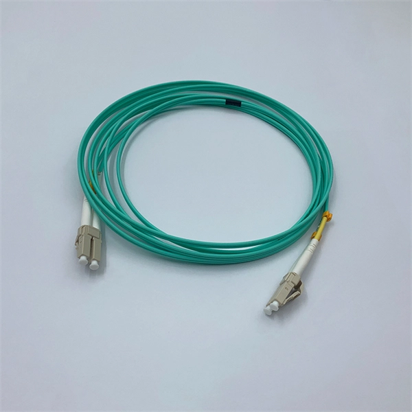
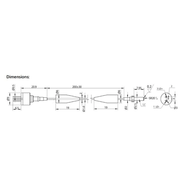
Utilizing proven LC ferrule technology, the SN® connector offers a threefold increase in fiber cabling density compared to traditional Duplex LC connectors — making it an ideal solution for high-density patching and advanced network architectures. The SN is ceramic-based fiber optic connector so compact and flexible that it can be utilized either as a Base-8 trunk solution, a Base-2 patching interface or as a Base-8 connection to next generation 200G, 400G, and 800G transceivers. Because size matters. SENKO's SN connector is a Very Small. Among these is a new connector known as SN® Connector, an advanced optic fiber designed for crowded places. The goal of this blog post is to take readers through everything they might want or need to know about SN® Connectors- we'll cover features and benefits so people can understand how it helps. SN® Connectors offer a compact 3. 1mm-pitch ferrule design and a convenient push-pull boot that enables easy access in high-density environments. 6mm or customizable 2mm cordage with G. A2 singlemode or OM4 multimode options, these assemblies meet industry standards and support. The Senko SN connector is a high-performance optical fiber connector designed for use in both telecom and data center applications. Such connectors are significantly smaller than their predecessors, like the SC (subscriber connector) or ST (straight tip) connectors. The reduced size doesn't mean a compromise.
[PDF]
A variety of optical fiber connectors are available, but SC and LC connectors are the most common types of connectors on the market. Typical connectors are rated for 500–1,000 mating cycles. The main differences among types of connectors are dimensions and. An optical fiber connector is a device used to link optical fibers, facilitating the efficient transmission of light signals. They come in various types like SC, LC, ST, and MTP, each designed for specific. Fiber connector types LC, SC, FC, ST, MTP, and MPO are widely used in past and present. What are the differences between them? Who is the most popular one? Find the answer in the article. What is a Fiber Connector? The optical fiber connector is a kind of detachable passive optical component used. Fiber optic cable assembly quality hinges on selecting the right connector type—most commonly LC, SC, or ST—to match device ports and installation environment. When selecting the appropriate optical module for a network application, one crucial factor to consider is the type of fiber connector it employs. Fiber optic connectors are used to the mechanical and optical means for cross connecting fibers. There have been many types of connectors developed for fiber cable. With the demands of different application scenarios.
[PDF]
The standard requirement for wire is 1. 5 to 2 feet for each square foot of the home; however, it may change depending on the project scope, needs, and demands. Whether you're quoting a panel upgrade for a new build or wiring a multi-unit commercial space, the numbers on your estimate aren't just guesses—they're the difference between staying profitable and bleeding hours on change orders. This guide lays out what it really takes to build accurate. In May 2026 the estimated national average cost to Install Electrical Wiring starts at $302 - $365 per wiring run. Use our Cost Calculator for cost estimate examples customized to the location, size and options of your project. Set Project Zip Code Enter the. It's natural to wonder about the bottom line, and understanding the electrical wiring cost per foot is the perfect place to start. When installed by a professional, this cost typically lands somewhere between $3 and $12. Here are the five steps to create a competitive electrical estimate. Early preparation. In electrical projects, preparing a professional electrical quote is an essential yet often time-consuming task. Calculating material costs, labor fees, and profit margins for electrical projects can be challenging, especially when meeting client expectations or managing revisions. The kitchen and the laundry area are the most power-consuming parts of the house.
[PDF]
These beamsplitters are made by coating the hypotenuse of dual prisms with a partially reflecting material and joining them together using optical or epoxy cement. They eradicate the ghosting phenomenon because the transmitted beam is consistent with the incident light beam. A beam splitter or beamsplitter is an optical device that splits a beam of light into a transmitted and a reflected beam. It is a crucial part of many optical experimental and measurement systems, such as interferometers, also finding widespread application in fibre optic telecommunications. This division allows for the simultaneous analysis or utilization of the light's properties along two separate paths. These tools can split both laser and regular light. Image Credit: Shanghai Optics Most plate beamsplitters are. 📦 For purchasing, use the RP Photonics Buyer's Guide for beam splitters. It provides an expert-curated supplier directory, buyer-focused technical background information, and structured selection criteria to support professional procurement decisions. Beamsplitters are often classified according to their construction: cube or plate. Beam splitters are used to manipulate and control light, making them valuable devices in both classical and quantum optics. A beam splitter is capable of introducing phase shifts and quantum superpositions, making them a core component of quantum technologies such as quantum computing and Quantum.
[PDF]
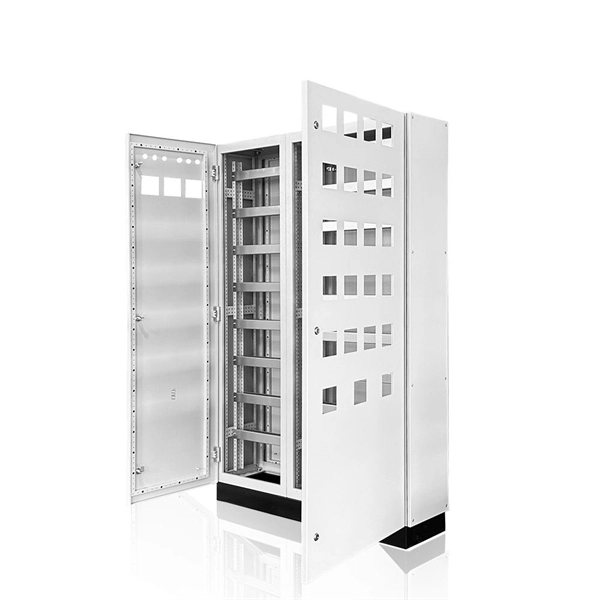
A distribution box, also known as a distribution panel or board, is a cabinet that holds electrical parts used to supply power to multiple circuits within a system. It acts as the central point where electricity distribution is managed inside a building. A distribution boxes is an essential device that manages the safe and efficient flow of electrical power throughout different areas of a building or facility. It is commonly used in homes, offices, and industrial settings to control and protect electrical circuits. It helps organize, protect, and control electrical connections in residential, commercial, and industrial electrical systems. To learn more about distribution boxes and how they work, keep. So, what is a distribution box? It organizes and controls power flow, ensuring safety and efficiency. By managing circuits individually, it prevents overloads and keeps your electrical setup running smoothly.
[PDF]
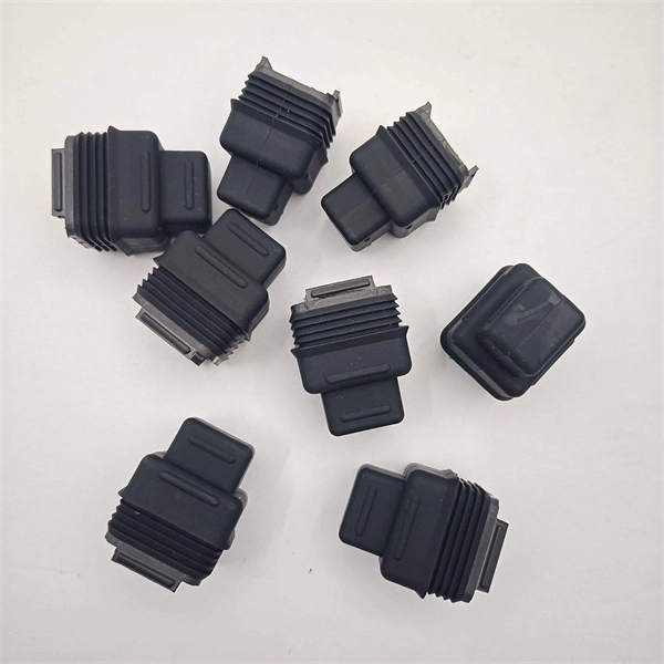
The adapter is instrumental in interfacing devices with fiber optic networks by converting optical signals to electrical signals, and vice versa. This guide covers adapter types, selection criteria, cleaning tips, FAQs, and B2B customization options to help businesses build reliable and scalable fiber networks. Fiber optic adapters may be small, but. Fiber optic networks rely on specialized cables that are designed to transmit data using light signals. Unlike traditional copper-based networks, fiber optic cables are made of ultra-thin strands of glass or plastic called optical fibers. These fibers are incredibly efficient at transmitting light. What is a Fiber Optic Network Adapters? A fiber optic network adapters, synonymous with a fiber optic NIC (Network Interface Card) or transceiver, is an intermediary that facilitates the connection between devices and fiber optic networks. They have a single fiber connector (simplex), dual fiber connector (duplex) or sometimes four fiber connector (quad) versions. Here's a detailed explanation of its usage: Fiber adapter panels house fiber optic adapters, which are essential for connecting fiber optic cables. They play a crucial role in linking optical fibers together, allowing for seamless transmission of data across vast distances. Whether you are setting up a new network or upgrading your existing one, understanding the.
[PDF]
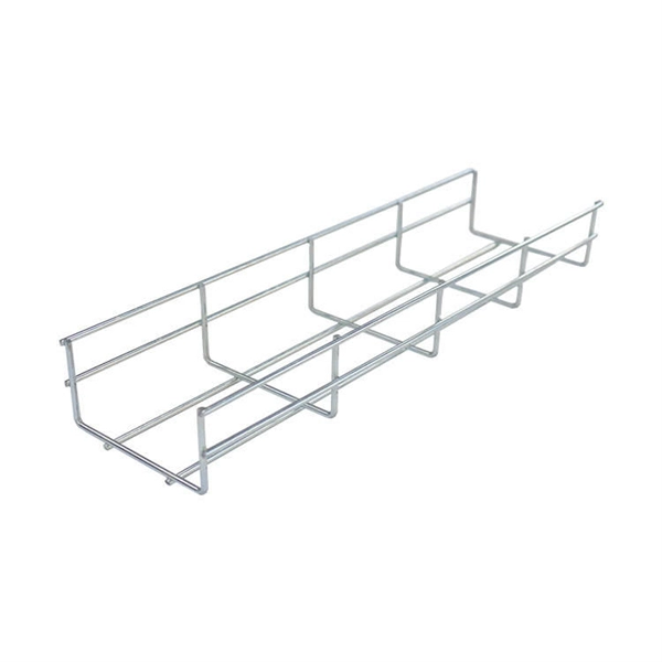
45° & 90° flat bends are available for light, medium and heavy duty cable tray systems with widths ranging from 50mm – 900mm. Different types of bends are essential to navigate obstacles, optimize space, and ensure the smooth and safe routing of cables in complex layouts. In this blog, we'll explore the various types of bends commonly used in wire mesh cable trays and discuss their applications and techniques in detail. Materials and finishes available are mild. Elbow Cover, 3/4", 1" Bend Radius, PVC, Office White, 1/bag Category: 90° Horizontal Cable Tray Bend Cable Runway Radius Bend; 12"W x 12. 5"L; Black; Cable Capacity - 947 Category: 90° Vertical Outside Tray Bend 90° Radius Juncture, 2 inch Depth x 12 Inch Width, Pre-Galvanized Steel. The bends, tees, crosses, risers and reducers of wire mesh cable tray can be easily and quickly made live at the project by using a bolt cutter. Since the jaws of the bolt cutter drags a layer of zinc across the cut end and forms a protective layer. An adjustable bend with 30°, 45°, 60°, 75° and 90° configurations is also available for medium and. Galvanized steel bends remain the standard for cost-effectiveness, with Shanghai Besca's $1/meter solution offering exceptional value for large projects. Their UL/CUL/CE certifications ensure broad compliance. For specialized environments, Foshan Huaxingwei's galvanized horizontal tees provide.
[PDF]
Optical fibers can be used as sensors to measure, , and other quantities by modifying a fiber so that the quantity to be measured modulates the,,, or transit time of light in the fiber. Sensors that vary the intensity of light are the simplest, since only a simple source and detector are required. A particularly useful feature of intrinsic fiber-optic sensors is that they can, if required, provide distributed sensing over very large distances.
[PDF]
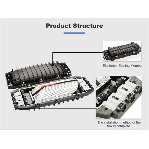
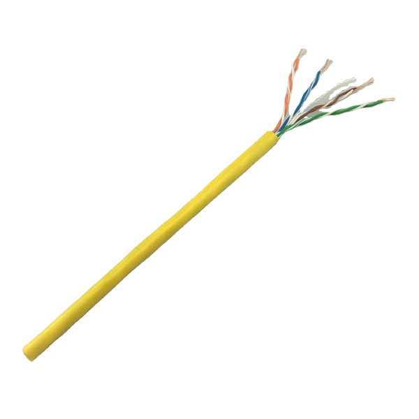
A fiber to Ethernet converter, often called a media converter, is a networking device that converts light signals from fiber optic cables into electrical signals used by Ethernet cables. This allows you to connect devices that use different types of cabling, such as a computer. An ONT, or Optical Network Terminal, is a device that converts fiber optic signals from your Internet provider into Ethernet signals that your devices can use. It's a key part of any Fiber to the Home (FTTH) setup. If your home uses cable Internet instead of fiber, you don't need an ONT. You'll use. For networking scenarios where the standard 100-meter reach of copper Ethernet cables (UTP or STP) is insufficient, Ethernet media converters for extended distance connectivity present a professional solution to extend connectivity. Connection Relationship: Step 1: Access outdoor fiber optic cables into fiber terminal box for the purpose of splicing the optical fiber cable and fiber optic.
[PDF]
This guide explores the top cable tray manufacturers in the Middle East and provides tips on making the best choice for your project. is one of the trustworthy Cable Tray Manufacturers in Palestine that is here to fulfill all your wire mesh and netting tools needs. We believe in building fruitful business partnerships. Every buyer chooses us first because of. Started back in 1983, Cable House is a recognized name engaged in manufacturing and supplying wide range including Hose Clamps, Cable Ties, Crimping Tools, Cable Tray, Industrial Connectors and more, to the national as well as the international market. With our manufacturing expertise, we have even. Keep your cables safe and organized with our high-quality cable trays. Cable Trays are important for ensuring the protection of the wiring system and supporting insulated electric cables used for distribution and communication. Brilltech Engineers Pvt. Ltd would be pleased to introduce itself as one of the leading Electrical Panel Manufacturers in Palestine. Our technology is up-to-the-mark and the technique we put in our process improves the quality and performance of our products and helps us. Transdelta, operating under the "Delta" brand, is a leading manufacturer of cable management systems, including cable trays, ladders, and trunking, primarily serving the Middle East market.
[PDF]
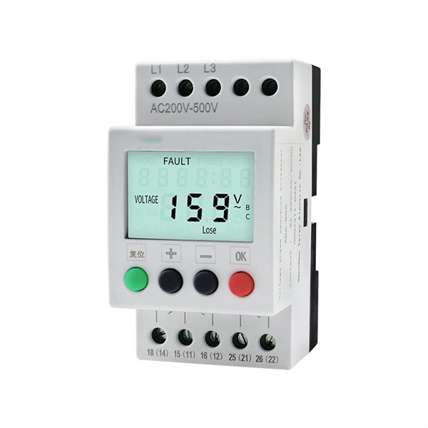
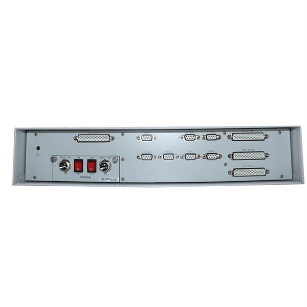
In this guide, we'll explore what protection relays are, how they're classified, the types available, and how they work with instrument transformers to create secure zones of protection. What Is a Protection Relay?. Protective Relay Definition: A protective relay is an automatic device that senses abnormal conditions in electrical circuits and triggers actions to isolate faults. Types of Protective Relays: Protective relays are categorized by their mechanism (electromagnetic, static, mechanical) and function. This article covers various types of protective relays, such as overcurrent, directional, and differential relays, highlighting their operating characteristics and applications in electrical systems. They don't just protect equipment; they ensure safety, prevent downtime, and save lives. A protective relay is a device that detects the fault and initiates the operation of the circuit breaker to isolate the defective element from the rest of the. The rectangular devices are test connection blocks, used for testing and isolation of instrument transformer circuits.
[PDF]
Easy-to-design and simple to assemble, Hilti's MT System offers an integrated solution with hardware, software, and services for mechanical, electrical, and pipe support systems along with industrial installations. An Electrician must know Electrical Abbreviations and Full Forms to read a electrical drawings. No matter is construction or maintenance your industry is, you need to be learned electrical abbreviations and electrical symbols. If you don't know you can't work with SLD drawings. What is the role of a cable tray in electrical engineering? A cable tray allows for the neat and aesthetic arrangement of cables, improves the reliability. At Hilti we can help from the moment you start your design to the moment you install the final solution. Whether you're planning MEP installations such as pipe and cable tray supports, or access platforms and integrated. us-trations without notice. All illustrations, descriptions and technical information included in this document are provided as indications and can cable trays are equivalent. The mechanical and electrical characteristics, tests, certifications, overall quality management, recommendations mentioned. In the electrical wiring of buildings, a cable tray system is used to support insulated electrical cables used for power distribution, control, and communication. Cable trays are used as an alternative to open wiring or electrical conduit systems, and are commonly used for cable management in.
[PDF]
Its primary role is to carry large current loads and connect multiple circuits together. Think of a bus bar as the main highway for electrical current—allowing it to flow between components with minimal resistance and voltage drop. In electric power distribution, a busbar (also bus bar) is a metallic strip or bar, typically housed inside switchgear, panel boards, and busway enclosures for local high current power distribution, transmission, or switching substations. Think. The electrical panel, often called the breaker box, functions as the central distribution point for all electricity entering a home. While circuit breakers are the visible safety components, the internal system that routes and distributes the power is built around the bus bar. It acts as a central hub, connecting multiple circuits and ensuring current flows efficiently. A busbar's main function is to conduct and distribute large electrical currents from one source to multiple circuits within an enclosure, acting as a central, high-capacity connection point. My insights show that understanding the practical function is key. As I've seen in the field, the textbook.
[PDF]
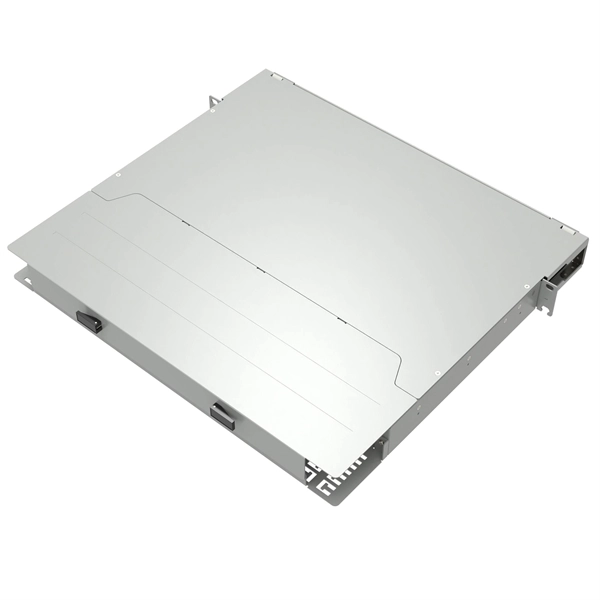
A Network Cabinet, often interchangeably called a server rack, is a physical frame or enclosure designed to house and organize various types of network hardware and accessories. This includes routers, switches, servers, patch panels, and other networking equipment. Not only a simple storage unit, a network cabinet is a key player in safeguarding and organizing critical network equipment. Whether you're setting up a new office or streamlining an existing network, understanding the importance, types, and usage of network cabinets is crucial. In this. Whatever location you choose, make sure it has adequate ventilation and is easily accessible. Once you've chosen the location, the next step is to select the right wiring cabinet. There are various options available, ranging from simple wall-mounted enclosures to larger floor-standing cabinets. Together, these reduce downtime by 18% and keep your IT infrastructure running smoothly. Let's explore each category in detail. When you set. Network server cabinets are the backbone of modern IT infrastructure, housing critical components that enable data processing, storage, and communication. The primary purpose of a network cabinet is to provide a centralized location where all. A network cabinet plays an essential role in the data center. Network cabinet helps improve cable management, physical security, ease of installation, etc. This article provides a simple guide to.
[PDF]