Its primary role is to carry large current loads and connect multiple circuits together. Think of a bus bar as the main highway for electrical current—allowing it to flow between components with minimal resistance and voltage drop. In electric power distribution, a busbar (also bus bar) is a metallic strip or bar, typically housed inside switchgear, panel boards, and busway enclosures for local high current power distribution, transmission, or switching substations. Think. The electrical panel, often called the breaker box, functions as the central distribution point for all electricity entering a home. While circuit breakers are the visible safety components, the internal system that routes and distributes the power is built around the bus bar. It acts as a central hub, connecting multiple circuits and ensuring current flows efficiently. A busbar's main function is to conduct and distribute large electrical currents from one source to multiple circuits within an enclosure, acting as a central, high-capacity connection point. My insights show that understanding the practical function is key. As I've seen in the field, the textbook.
[PDF]
The fiber optic adapter is also called a flange or fiber optic connector. It is usually assembled on various adapter panels and chassis. The Fiber Optic Flange, also known as a Fiber Optic Adapter or Fiber Optic Coupler in engineering, is one of the most fundamental and essential passive devices in fiber optic communication systems. Simply put, it acts like a transition socket or connector adapter in electrical circuits. Important optical fiber connection. Fiber optic adapters are often treated as simple passive interfaces, but their mechanical interaction with the mounting panel plays a critical role in long-term alignment stability and service reliability. The distinction between flanged and flangeless adapters is purely mechanical. It does not. What is a fiber optic connector? The function of fiber optic connectors is to align and connect two or more fibers together to provide a means for attaching to, or decoupling from, a transmitter, receiver, or any other fiber optic component. Most fiber optic connectors are composed of. An optical fiber flange is a type of optical fiber connector used to attach optical fiber cables to other equipment, such as patch panels or network switches. It is designed to provide a secure and reliable connection between optical fibers, minimizing signal loss and ensuring high-quality.
[PDF]
The Huawei OEGD01N01 is an Optical Functional Module known for its robust functionality in networking environments. It is a 1000BASE-T-SFP Module featuring an RJ45 Electrical Module with auto-negotiation capabilities. Optical modules are widely used in switches, network interface cards (NICs), routers, and other communication devices. During use, reading optical module information helps understand its real-time operating status, enabling faster troubleshooting of link abnormalities. The following uses the. A switch must use optical or copper modules that have been certified for use on Huawei switches. Non-certified optical or copper modules cannot ensure transmission reliability and may affect service stability. Designed for optimal performance, it supports a longest transmission distance of. OLT is the world's first Terabit fiber access system. With the pending support for XG-PON1 (10Gbps downstream and 2. 5Gbps upstream data rates) technology, Huawei's MA5600T OLT is designed to provide even higher subscriber bandwidth in shared fiber splitter applications. Huawei's all-in-one fiber. TX/RX power test ensures that the optical power are within the thresholds; remove the aged optical module with power loss, and the fake module with counterfeit label. Huawei is not liable for any problem caused by the use of non-certified optical or.
[PDF]
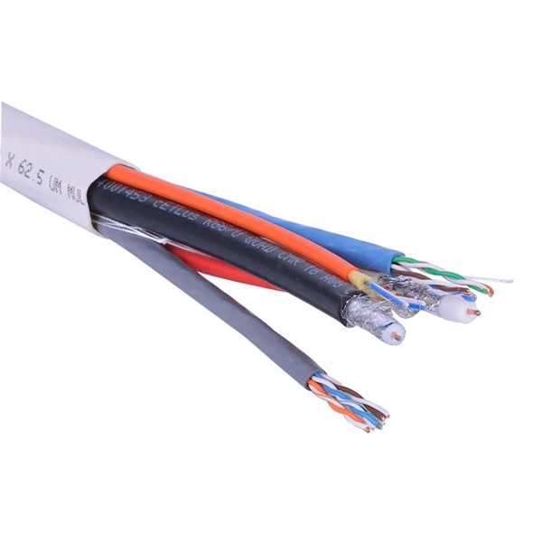
Several common cable outer sheath materials are PVC, PE, LSZH, AT and rodent-proof sheath materials. PVC is the most widely used fiber optic cable outer sheath material. What Is a Cable Sheath and Why It Matters 🔍 The cable sheath is the outer protective layer of a fiber optic cable. Its primary functions include: While the optical fiber itself remains largely unchanged, the sheath material determines how the cable behaves in fire scenarios, outdoor environments. The main function of the fiber cable outer sheath is to protect the optical fibers in the optical cable from external damage. At the same time, it must have. PVC vs LSZH vs TPU: Which sheath material for fiber optic cables in 2026? The jacket material determines the reliability, fire resistance, and lifespan of a fiber optic cable. At the same time, it must have. If so, then do remember that Fiber cables are made with high-grade glass cores and environmental protective sheaths, which can endure everything from residential network connections to underwater links. In this article, we'll discuss in detail the construction of Fiber optic cables and also see the. The sheath or outer sheath is the outermost protective layer in the optical cable structure, mainly made of PE sheath material and PVC sheath material, and halogen-free flame-retardant sheath material and electric tracking resistant sheath material are used in special occasions.
[PDF]
Find and discover Fiber Optic manufacturers and suppliers for all products in Laos, featuring details on their shipment activities, trade volumes, trading partners, and more. View all fiber optic buyers based on products in Laos. Subscribe to global trade data intelligence to discover new business. WWCC is upgrading the products operations through research, advanced technology and machinery, to serve the expanding needs of Laos's economy at competitive prices. The company is committed to offer high quality products to achieve customers' satisfaction. Our fiber optic cables are designed for use in laser surgery, endoscopy, photodynamic therapy, and diagnostic imaging, ensuring superior light transmission. How does 6W market outlook report help businesses in making decisions? 6W monitors the market across 60+ countries Globally, publishing an annual market outlook report that analyses trends, key drivers, Size, Volume, Revenue, opportunities, and market segments. Our insights help.
[PDF]
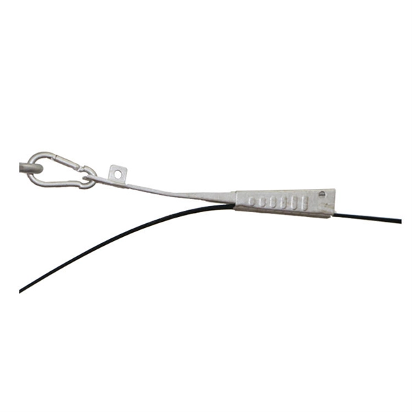
The vertical clearance for overhead fiber optic lines above the highway must be a minimum of 18 feet. The exception is ADSS cables which are approved for installation in the power space by qualified personnel. All aerial cables should be installed clear of any obstructions. The Fiber Optic Association, Inc. (FOA) was founded in 1995 to help develop the workforce to build the fiber optic networks to support a rapid expansion in communications and the Internet. The charter of the FOA was to promote professionalism in fiber optics through education, certification, and. The basic pole height is 7m and the tip diameter is 150mm. In case of special sections, crossing obstacles or roads or railways, the pole height of 8m, 9m, etc. can be selected according to the actual terrain. If the surface is stone, the depth needs to be 0. 9m, and if the surface is other soil. Generally a 12 inch to 24 inch soil separation is recommended as a safety barrier and for locating purposes. 9938 | SuperiorEssexCommunications. com Page 1 of 4 TECHNICAL GUIDELINE July 30, 2020 TG030 Rev. FIBER is used for relocating any fiber optic cable from one location to another. Field conditions will vary, so the actual location. to n utral comm.
[PDF]
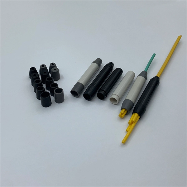
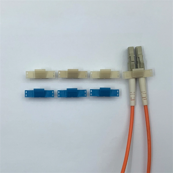
Fiber optic pigtails are roughly divided into two categories: Multimode and single-mode fiber pigtails. Multimode pigtails consist of 62. 5 or 50-core multimode fiber optic cables that are terminated with multimode connectors. To classify them further, they can be subdivided into OM1. This guide covers everything: what fiber optic pigtails are, how they differ from patch cords, which connector and polish type to specify, how to choose between mechanical and fusion splicing, and the real-world applications where pigtails are the right call. Whether you're building out an ODF. A fiber optic pigtail is a short length of optical fiber —typically 0. 5m to 2m—that has a factory-terminated connector on one end and bare fiber on the other end. The connector end is polished and tested under factory conditions, ensuring low insertion loss and high return loss. The bare fiber end. Understanding the different models and characteristics of fiber pigtails can help users better match system requirements in practical applications and ensure efficient and stable fiber optic communications. The connector end can be linked directly to network equipment, while the exposed end can be spliced to another fiber optic cable. In this comprehensive guide, we explore the different types of fiber optic pigtails available, including MU, LC, SC, FC, DIN, APC, and UPC.
[PDF]
The V-groove substrate is the heart of the Fiber Array, providing precise alignment for the optical fibers. This substrate, typically made from silicon, glass, or ceramic, features a series of V-shaped grooves etched with sub-micron accuracy. Fiber Array (FA for short) is an array formed by installing a bundle of optical fibers or a fiber ribbon on the substrate at specified intervals by using a V-Groove (V-Groove) substrate. Fiber optic arrays in optical communications mainly include a substrate, a platen, and an optical fiber. Whether integrated into planar lightwave circuits (PLCs), optical switches, or high-speed transceivers, FAs play a vital role in ensuring. What is a Fiber Array (FA)? A Fiber Array, commonly abbreviated as FA, is a critical interface component in Silicon Photonics (SiPh) packaging, Photonic Integrated Circuits (PIC), and Co-Packaged Optics (CPO) architectures. It is responsible for efficiently coupling "external optical fibers" with. Fiber Arrays (FAs), as high-precision, high-performance optical components, have become indispensable core elements in fields such as optical communications, photonic integration, and laser processing. Typically, such an array is formed only for the very end of the fibre bundle, rather than over the entire length of the.
[PDF]
Fiber optic "cable" refers to the complete assembly of fibers, other internal parts like buffer tubes, ripcords, stiffeners, strength members all included inside an outer protective covering called the jacket. Cable provides protection for the optical fiber or fibers within it appropriate for the environment in which it is installed. You will also learn how different aspects of the product can affect budget and design. ■ The Five Key Parts of a Fiber Optic Cable A fiber optic cable. A fiber optic cable consists of five basic components: the core, the cladding, the coating, the strengthening fibers, and the cable jacket. When searching for a fiber optic cable, we need to pay attention not only to the connectors, such as SC to ST fiber cable, LC to SC fiber patch cable, or SC to. A TOSLINK optical fiber cable with a clear jacket. These cables are used mainly for digital audio connections between devices. This advanced cabling solution allows fast, secure data transfer and telecom over long distances. Understanding the components within a fiber optic cable enables. While fiber optic cable itself is cheaper than an equivalent length of copper cable, fiber optic cable connectors and the equipment needed to install them have typically been more expensive than their copper counterparts.
[PDF]
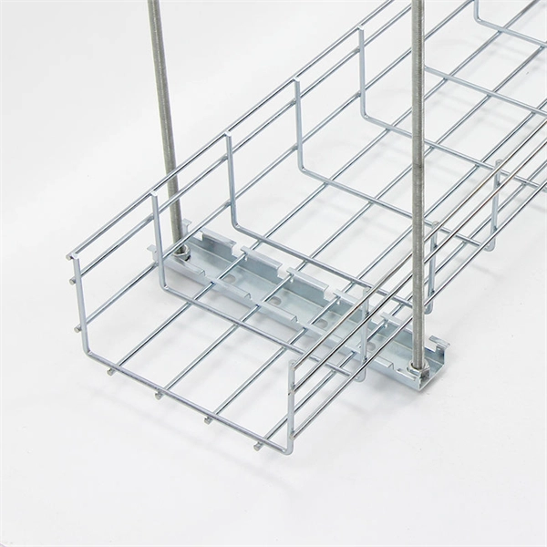
This section provides an overview for wire mesh trays as well as their applications and principles. Here are the top-ranked wire mesh tray companies as of April, 2026: 1. Code Electric Products Ltd. Brilltech Engineers Pvt. brings the Cable Trays in Greece just for you! We, one of the well-known Cable Trays Manufacturers in Greece, offer top-notch trays that keep your electrical system organized and protected. Our durable, high-quality trays come in various sizes and styles to fit any. METAKSAN ELEKTRIK; produces and supplies many electrical materials such as cable protection and carrying systems, grounding and lightning protection equipment, distribution boxes and industrial sockets. METAKSAN ELEKTRIK; With its years of experience and customer-oriented service policy, with its. Cable trays are a mechanical support system that can support electrical cables used for power distribution, control, and communication. They are the perfect solution for running large quantities of power or data cables overhead or under-floor. Cable tray for cable support. This comprehensive list of top 10 online B2B marketplaces and manufacturers will lead you to find your perfect cable trays based on your business requirements. Let's explore the characteristics of these platforms together. com provides buyers with a free hand to explore customized cable.
[PDF]
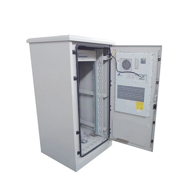
A spider box is a portable electrical distribution box that is commonly used with temporary and emergency power infrastructure. It's called a “spider box” because cables from all sides are distributed out to different parts of the job site which resemble that of a spider's legs. This article explains how temporary construction power boxes work, the key components involved, and how E-abel portable electrical enclosures combined with industrial connector systems enable efficient, safe, and scalable power distribution for construction projects. Walk onto any construction site. Every construction site relies on one essential thing to keep operations moving— power. Whether it's lighting, heavy-duty tools, or on-site offices, electricity needs to be distributed safely and efficiently. Often overlooked. Temporary power distribution boxes are a budget-friendly way to supply electricity to a remote area. You can use them to power electrical equipment, lighting systems and more. These versatile units work great for construction sites, entertainment events, and disaster recovery operations. Power outages a problem? Count on Power Temp Systems solutions, tailored to your needs, to keep your project on schedule and ensure your team has all the.
[PDF]
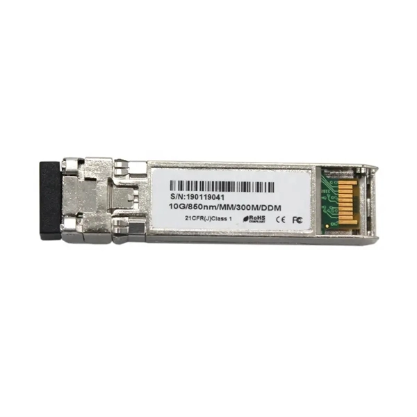
TX and RX in SFP refer to the transmission (TX) and reception (RX) of data signals over a fiber optic cable using Small Form-factor Pluggable (SFP) modules. TX converts electrical signals into optical signals while RX converts optical signals back to electrical signals. SFP (Small Form-Factor Pluggable) modules are compact transceivers that allow for high-speed communication between network devices. They are essential in applications like telecommunications, data centers, and enterprise networks. SFP modules are available in optical and copper variants, and they. In optical communication systems, the transmit power and receive power of an optical transceiver are among the key indicators used to evaluate link quality and module operating status. They play an important role during new link deployment, compatibility testing, and link troubleshooting. These modules are inserted into SFP ports on a switch. SFP ports are similar to RJ45 connector ports used to connect copper cables. Receive power is the power at which the receiver of an optical transceiver module receives optical signals, in dBm. When the signal received is outside of the range, there is a. Tx power (transmission power) refers to the intensity of the optical signal output by the transmitting end of the optical module. However, in practical use, we adopt the average Tx power. These links can span 10 to 15 kilometers. For longer distances, like 40 to 80+ km, 1550nm transceivers.
[PDF]
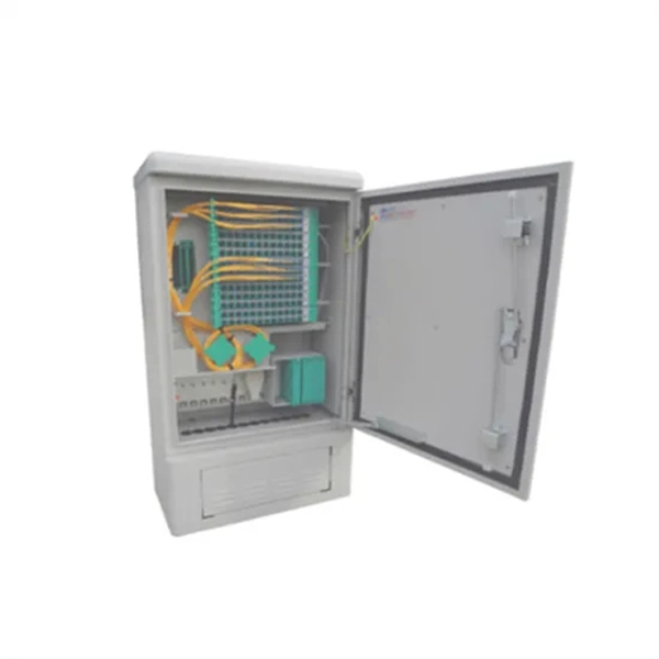
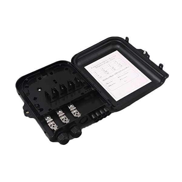
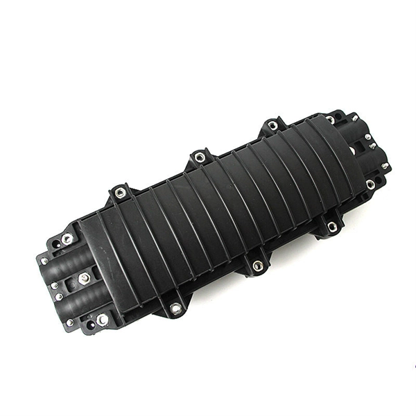
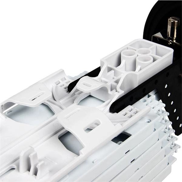
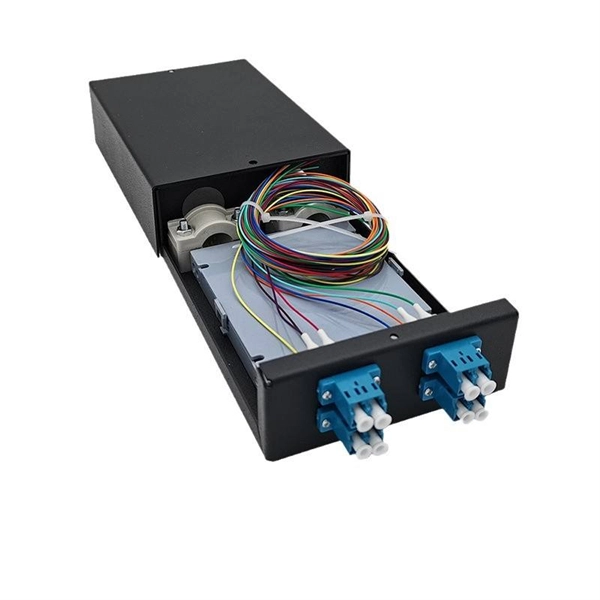
Our products cover MPO connectors, optical time-domain reflectometers (OTDR), optical cable joint boxes, optical fiber distribution boxes, optical cable cross-connect cabinets, etc. We provide comprehensive optical communication solutions and are a professional optical fiber. Haian Guangyi Communication Technology Co. specializes in manufacturing a full range of passive optical components, including optical splitters, optical fiber connectors, ODN products, and optical communication test instruments. These sequences are similar to bacterial DNA and are recognized by Toll-like receptor 9 (TLR9), an essential component of the innate immune. ODU series ODF sub-rack could be classified to integrated splicing & termination sub-rack and separated splicing & termination sub-rack. It usually is used in ODF rack or other telecommunication cabinets. ) specializes in providing the complete FTTH Product Series, ensuring that every decibel of optical power is preserved from the core to the customer. A standard FTTH ODN is divided into four critical segments. Weunion provides. CpG oligodeoxynucleotides (CpG ODNs) are synthetic DNA molecules characterized by short, single-stranded structures containing unmethylated CpG motifs derived from bacterial DNA. Pre-clinical studies and trials have demonstrated that CpG ODNs can significantly improve vaccine-specific antibody responses. CpG ODNs possess a partial or complete phosphorothioate.
[PDF]
Picking up the best router for fiber internet isn't just about going to the market and choosing one of the best wireless routers. Instead, you need to carefully look at its specs, performance, and the type of securit.
[PDF]

Thinner cables can be utilized to connect the control switch to the relay; this saves space, weight, and cost. The same voltage and current ratings as other types of switches, such as mechanical switches, do not limit relays. This handbook covers the code of practice in protection circuitry including standard lead and device numbers, mode of connections at terminal strips, colour codes in multicore cables, dos and donts in execution. Also principles of various protective relays and schemes including special protection. A control relay is an electrically operated switch that enables current to flow through a coil that closes or opens the switch. Relays use a small current to control a larger current, making them ideal for controlling high-power devices such as motors, lights, valves, and sensors. When a relay contact is open, this will switch power ON for a circuit when the coil is activated. You'll connect a low-power control circuit to the relay's coil (terminals 85 and 86), which then flips a switch for a separate, high-power circuit running through the. Electrical protection relay has two type protecton as HT panel protection and LT panel protection. HT panel protection relay. The HT power supply is received from GO switch and distributed to the. The rectangular devices are test connection blocks, used for testing and isolation of instrument transformer circuits. : 4 The first protective relays were electromagnetic.
[PDF]