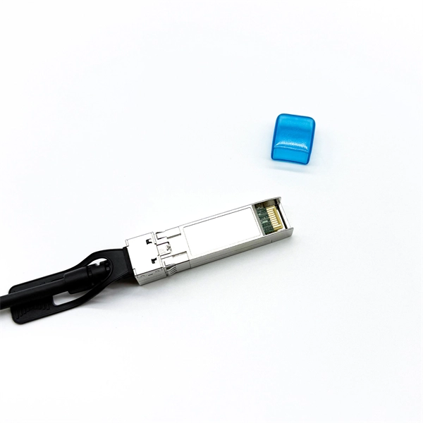
It supports multi-mode fiber with a reach of 300m via a duplex LC connector. Designed for extended temperatures (-40°C to 85°C), it includes Digital Optical Monitoring (DOM) and guarantees full compatibility with H3C equipment, making it ideal for harsh environment deployments. Optical modules transmit signals over optical fibers. Optical transmission features low loss and is fit for long distance transmission. The. Max. Note: Due to DigiKey value-add services the packaging type may change when product is purchased at quantities beneath the standard package. Buy now, ships today. SFP-XG-SX-MM850-D-C - Transceiver Module Networking and Communications 10Gbps 850nm LC Duplex Pluggable, SFP+ from ATGBICS. View. This H3C® SFP-XG-SX-MM850-A compatible SFP+ transceiver provides 10GBase-SR throughput up to 300m over multi-mode fiber (MMF) using a wavelength of 850nm via an LC connector. Our transceiver is built to meet or exceed OEM specifications and is guaranteed to be 100% compatible with H3C®. With a data rate of 10. This transceiver is compliant with SFF-8431, SFF-8432 and IEEE 802. 3ae standards and for seamless interoperability in multivendor environments.
[PDF]
Joints between high-current bus sections often have precisely machined matching surfaces that are silver-plated to reduce contact resistance. At extra high voltages (more than 300 kV) in outdoor buses, corona discharge around the connections becomes a source of radio-frequency interference and power loss, so special connection fittings designed. OverviewIn , a busbar (also bus bar) is a metallic strip or bar, typically housed inside,, and for local high current power distribution, transmission, or switching s. The busbar's material composition and cross-sectional size determine the maximum current it can safely carry. Busbars can have a cross-sectional area of as little as 10 square millimetres (0.016 sq in), but. • – Data transfer channel connecting parts of a computer• – Low resistance electrical conductor for high current transmission and distribution• – Modular approach t.
[PDF]
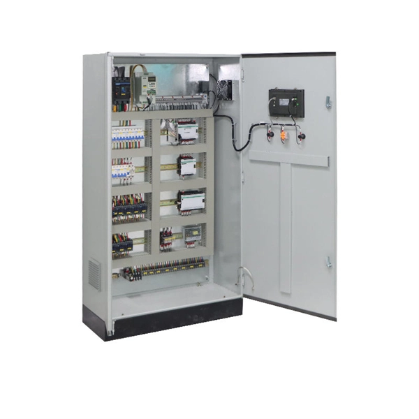
A protection relay tripping circuit connects relays to breakers for fast fault isolation. Key components include trip/close coils and anti-pumping relays. Proper design, testing, and maintenance ensure reliable overcurrent, differential, and auto-reclosing protection in power. The protection relay tripping circuit refers to the critical electrical control loop that executes trip/close commands from protective relays to circuit breakers, ensuring rapid fault isolation in power systems. Essential. Electromechanical protective relays at a hydroelectric generating plant. The relays are in round glass cases. In electrical engineering, a protective relay is a relay device. A protective relay is an intelligent electrical device designed to detect faults in power systems and initiate corrective actions such as tripping a circuit breaker. Its main purpose is to safeguard electrical equipment like transformers, generators, and transmission lines from damage due to. By definition, a protective relay is a switchgear device that detects faults and initiates the circuit breaker operation to isolate the problematic component of the system. Electrical values are measured by these relays to determine abnormal circumferences of a circuit. It functions as a watchdog by constantly surveying multiple system components including voltage, current, frequency, and phase angle.
[PDF]
Underground fiber optic cable installation follows specific standards that govern burial depth, testing methods, installation techniques, and safety requirements. Underground cables are pulled in conduit that is buried underground, usually 1-1. 2 meters (3-4 feet) deep to reduce the likelihood of accidentally being dug up. In extreme cold climates, cables may need to be buried at greater depths where there temperatures are colder and frost penetrates to. The Fiber Optic Association, Inc. (FOA) was founded in 1995 to help develop the workforce to build the fiber optic networks to support a rapid expansion in communications and the Internet. The charter of the FOA was to promote professionalism in fiber optics through education, certification, and. This guide walks through each stage of underground fiber installation—from route planning and conduit selection to splicing, termination, and testing—to help ensure long-term network performance and reliability. These standards, established by organizations like the National Electrical Code (NEC), National Electrical Safety Code (NESC), and. Installing underground fiber optic cables is critical to establishing high speed internet infrastructure that delivers reliable connectivity for businesses nationwide. Unlike traditional copper systems, fiber optic cables require specialized handling techniques and precise installation methods to.
[PDF]
As illustrated in typical SFP internal structure diagrams, the module's core components include an optical transmitter assembly (TOSA), laser driver, optical receiver assembly (ROSA)—some high-sensitivity modules (like L16. 2) use APD receivers, which require an additional booster. As a key element in optical communication systems, optical transceivers serve as media between network devices to transmit and receive data. There has been lots of articles and guides on transceiver modules in the perspective of the package type while only a few of them cover the internal elements. Optical modules are devices used to connect network devices, transmit and receive data between network devices, and can be used to convert optical and electrical signals. The optical module is a very important component in an optical communication system. When you remove the metal housing of the optical transceiver, you will find that the internal components are connected to each other. The following section will focus on. In the era of 5G, AI, and high-speed data centers, optical modules serve as the core bridge for converting electrical signals to optical signals (and vice versa), enabling fast, reliable data transmission across networks. Among various optical module form factors, SFP (Small Form-Factor Pluggable). The optical transceiver module is mainly composed of three parts: housing, optical device and integrated circuit board. The following section will focus on.
[PDF]
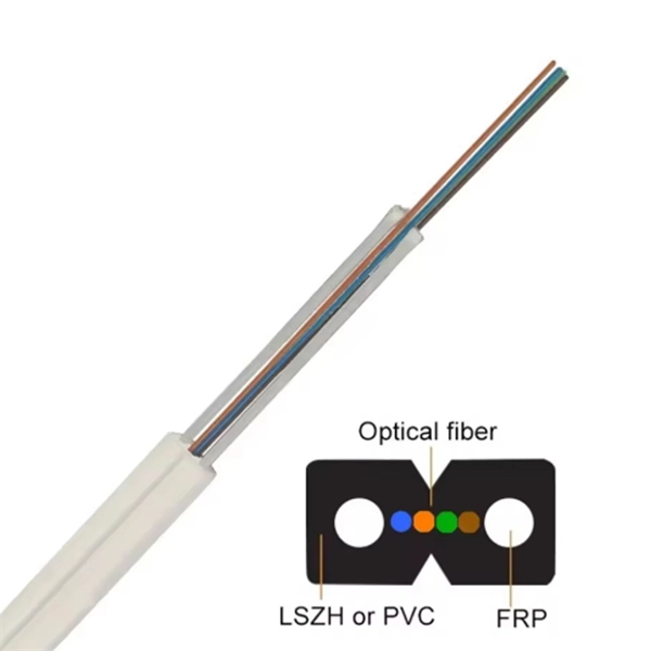
Fiber optic "cable" refers to the complete assembly of fibers, other internal parts like buffer tubes, ripcords, stiffeners, strength members all included inside an outer protective covering called the jacket. Cable provides protection for the optical fiber or fibers within it appropriate for the environment in which it is installed. You will also learn how different aspects of the product can affect budget and design. ■ The Five Key Parts of a Fiber Optic Cable A fiber optic cable. A fiber optic cable consists of five basic components: the core, the cladding, the coating, the strengthening fibers, and the cable jacket. When searching for a fiber optic cable, we need to pay attention not only to the connectors, such as SC to ST fiber cable, LC to SC fiber patch cable, or SC to. A TOSLINK optical fiber cable with a clear jacket. These cables are used mainly for digital audio connections between devices. This advanced cabling solution allows fast, secure data transfer and telecom over long distances. Understanding the components within a fiber optic cable enables. While fiber optic cable itself is cheaper than an equivalent length of copper cable, fiber optic cable connectors and the equipment needed to install them have typically been more expensive than their copper counterparts.
[PDF]
At present, key breakthroughs in optical fiber communication technology include high-order modulation formats, polarization multiplexing, wavelength division multiplexing, etc. Optical fiber communication can be widely applied in the fields of the internet and telephone networks . With the rapid development of cloud computing, big data, the Internet of Things, and other new technologies, we have entered an era of digitalization and informatization. The number of internet users has been steadily increasing, which has accelerated the exponential expansion of data services. A. Then the different technologies in optical fiber communication along with their features are discussed briefly.
[PDF]
Several common cable outer sheath materials are PVC, PE, LSZH, AT and rodent-proof sheath materials. PVC is the most widely used fiber optic cable outer sheath material. What Is a Cable Sheath and Why It Matters 🔍 The cable sheath is the outer protective layer of a fiber optic cable. Its primary functions include: While the optical fiber itself remains largely unchanged, the sheath material determines how the cable behaves in fire scenarios, outdoor environments. The main function of the fiber cable outer sheath is to protect the optical fibers in the optical cable from external damage. At the same time, it must have. PVC vs LSZH vs TPU: Which sheath material for fiber optic cables in 2026? The jacket material determines the reliability, fire resistance, and lifespan of a fiber optic cable. At the same time, it must have. If so, then do remember that Fiber cables are made with high-grade glass cores and environmental protective sheaths, which can endure everything from residential network connections to underwater links. In this article, we'll discuss in detail the construction of Fiber optic cables and also see the. The sheath or outer sheath is the outermost protective layer in the optical cable structure, mainly made of PE sheath material and PVC sheath material, and halogen-free flame-retardant sheath material and electric tracking resistant sheath material are used in special occasions.
[PDF]
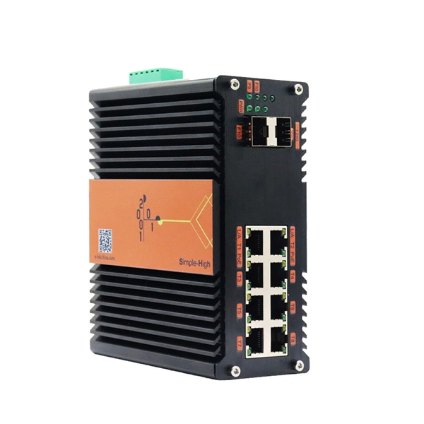
A fiber optic transceiver (also called an optical transceiver) is a compact module that both transmits and receives data signals through optical fibers. It serves a dual purpose — transmitting electrical signals as light pulses and receiving light pulses to convert them back into. Fiber optic communication systems use light pulses to transmit information over long distances via optical fibers. These systems rely on three vital components working together – the communication channel, the optical transmitter, and the optical receiver. The optical fiber cable itself makes up. They consist of a transmitter on one end of a fiber and a receiver on the other end. Most systems operate by transmitting in one direction on one fiber and in the reverse direction on another fiber for full duplex operation. Most systems use a "transceiver" which includes both transmission and. A fiber optic cable consists of five basic components: the core, the cladding, the coating, the strengthening fibers, and the cable jacket. Fiber optics deals with study of propagation of light through transparent dielectric wageguides. The fiber optics are used for transmission of data from point to point location. Such fibers are widely used in fiber-optic communication, where they permit transmission over longer distances and at higher bandwidths (data transfer rates) than.
[PDF]
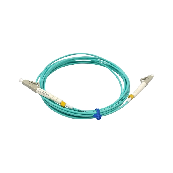
A fiber optic pigtail is a short length of optical fiber —typically 0. 5m to 2m—that has a factory-terminated connector on one end and bare fiber on the other end. The connector end is polished and tested under factory conditions, ensuring low insertion loss and high return loss. They are the bridge between fiber optic cables in the field and the equipment or patch panels that manage them. By combining factory-installed connectors with spliced bare fiber, pigtails ensure that network installers can create fast, reliable, and cost-effective terminations. Without pigtails. What is a Fiber Optic Pigtail, and What Is It Used For? Written by Ben Hamlitsch, trueCABLE Technical and Product Innovation Manager RCDD, FOI A fiber optic pigtail is a type of fiber optic cable with only one end that has a factory-terminated connector and the other end exposed as bare fiber. ) fitted on one end and the other end undressed (for connection through fusion or splicing) to the main fiber optic cable. It is usually suitable for field termination using a mechanical or fusion splicer. Compared with quick termination or epoxy and polish connections placed on the field. Fiber optic pigtail offers an optimal way to joint optical fiber, which is used in 99% of single-mode applications. This post contains some basic knowledge of fiber optic pigtail, including pigtail connector types, fiber pigtail classifications.
[PDF]
For such cables, we recommend using at least a 1. 5-inch conduit, and sometimes a 2-inch conduit may be necessary. It's important to consider not only the rigidity of the jacket but also the breakout point of the assembly, where the strands exit the jacket and are encased in. For such cables, we recommend using at least a 1. Selecting the appropriate conduit size is crucial and depends on the type of jacket on your cable assembly and the. Premise innerduct is a flexible, non-metallic, corrugated raceway that has long been an essential conduit system for protecting fiber optic cables installed throughout telecommunications spaces and pathways. Conduit also facilitates cable management and ease of maintenance. With these assemblies we mention in this article, the widest point. This calculator will allow you to find the fill ratio using one, two, or three cables within the conduit. If you only have one cable for your conduit, please use only the first cable diameter field. Once the fill ratio calculator is computed, the program tells you if it falls within Corning's. Calculation Method 1 – Calculate the minimum conduit size required for a specific number of cables. This is particularly useful when planning an installation. (Equation 1 below) Calculation Method 2 – Calculate the maximum number of cables that can be installed in a conduit of a known size. Next, select the type of conduit you are specifying. " To determine the size of.
[PDF]
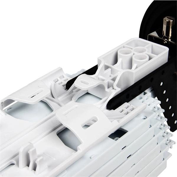
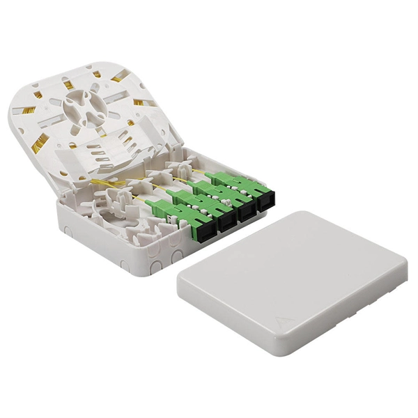
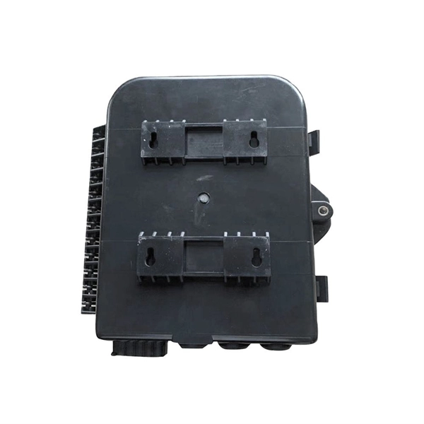
The centralized splitter approach typically uses a 1×32 splitter in an outside plant (OSP) enclosure, such as a fiber distribution terminal. The 1×32 splitter is directly connected via a single fiber to an OLT in the central office. They are typically installed in each optical network between the PON OLT (optical line terminal) and ONTs (optical network terminals) that the OLT serves. Generally, two kinds of fiber optic splitters are popular, which are FBT splitters and PLC splitters. The differences between the two have been. A fiber broadband provider typically determines and overall split ratio for the network, such as 1x32 or 1x64, and uses combinations of splitters to meet that ratio with each PON port. 1x32 splits were common in North America for G-PON architectures. As XGS-PON continues to be adopted, some service. This comprehensive guide explains how optical splitters work, what types are available, and how to select the optical splitter best buy or optical cable splitter best buy for your network deployment. What Is a Fiber Optic Splitter? A fiber optic splitter is a passive optical component designed to. Star couplers are used for their uniform splitting, while WDM splitters are used to split light beams of different wavelengths. Application Areas Fiber optic splitters are used in various areas, including active optical networks, passive optical networks, FTTX access networks, and measurement.
[PDF]
Fiber optic bundles consist of multiple optical fibers grouped together to transmit light signals simultaneously. These bundles are integral to various applications, including imaging systems, illumination, spectroscopy, sensors, and high-speed data transmission across diverse. A fiber optic bundle, (also known as a light guide or light pipe), is a multiplicity of single optical fiber strands. When this multiplicity of fibers is randomly gathered, it is usually collected in a jacket (buffer, sheathing, housing) and held together at each end with epoxy to form an output or. What is a Fiber Bundle? For some applications, some number of optical fibers is bundled together, forming a fiber bundle or fiber-optic bundle. In most cases, one uses multimode large-core silica fibers or plastic fibers. As technology advances and the demand for high-speed internet increases, understanding the fundamentals of fibre cable bundling becomes. Ribbon fiber optic cable is a type of optical fiber cable that consists of multiple individual fibers arranged in parallel within a flat ribbon-like structure. Instead of having individual round cables, ribbon cables have several fibers laid out side by side, typically in a flat and compact. A fiber optic bundle is designed to transmit light or image in the visible region of the spectrum. This article is going to introduce fiber optic bundles, and it is configuration examples, benefits, and applications.
[PDF]
Gigabit is a decimal unit defined as per SI standard. 1 Gigabit = 1000 Megabits. The unit symbol for Gigabit is Gbit or Gb. Abbreviated as Gb, a gigabit is a method of measuring data transmission. When the "b" is uppercase, like GB, this refers to a gigabyte. What comes before a gigabit? What comes after a gigabit? Gigabit vs. other data measurements. What comes before a. Gigabit single-mode fiber optic module Common parameters of optical modules 1. Center wavelength 1) 850nm (MM, multi-mode, low cost, but short transmission distance, usually only 500M); 2) 1310nm (SM, single mode, large loss during transmission, small dispersion, generally used for transmission. In computer networking, Gigabit Ethernet (GbE or 1 GigE) is the transmission of Ethernet frames at a rate of a gigabit per second. The most popular variant, 1000BASE-T, is defined by the IEEE 802. It came into use in 1999 and has replaced Fast Ethernet in wired local networks due to. What is 1 Gig in Mbps? 1 Gigabit (Gb) is equal to 1000 Megabits (Mb). This conversion is important to understand because data transfer rates are commonly measured in Mbps, but many internet plans, network devices, and even transceivers are rated in Gbps. So. A gigabit (Gb) is a unit of digital information equal to 109 bits, or 1,000,000,000 bits. It uses the standard SI decimal prefix 'giga-'. It is important to distinguish.
[PDF]
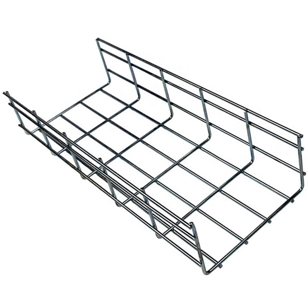
Trapezoidal Cable Tray: Trapezoidal cable trays are characterized by their trapezoidal structure consisting of two side rails connected by a crosspiece. This design allows for excellent ventilation and heat dissipation, making them ideal for high-capacity cable management. Cable trays are essential components in electrical installations that provide a structured path for cables and keep them safe and organized. They are widely used in commercial, industrial, and residential settings to support and protect wiring systems. Understanding the different types of cable. Cable tray systems are engineered support structures designed to route, support, and protect insulated electrical cables used for power distribution, control, instrumentation, and communication. Unlike conduit systems, cable trays allow cables to be laid in bundles, improving accessibility, heat. What is Cable Tray Systems? 1. Perforated Cable Tray 3. These trays have large space and good ventilation performance. Understanding the different types of cable. According to the National Electrical Code standard of the United States, a cable tray is a unit or assembly of units or sections and associated fittings forming a rigid structural system used to securely fasten or support cables and raceways. Several types of tray are used in different.
[PDF]