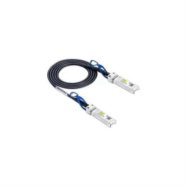
These modules are engineered with high-grade components designed to withstand the vibrations of washboard forest service roads and the temperature swings of high-altitude passes. 00 Original price was: $46. Activates High current relay when High Beams are turned on, used to add large light bars and driving lights without having to install additional switches in the dash. Plugs directly into Polaris Pulse System for switch lighting and keyed on ignition. The CanM8 Cannect Duo (Speed Pulse & High Beam) Interface is a 2-output CAN Bus interface which provides a quick solution for detecting high beam activity on vehicles which feature CAN Bus wiring. The Cannect Duo Interface also features a square pulsed speed signal output from the vehicle at a. Electronic technology has advanced so that an electronic control unit (ECU) is required to control the functions of full LED automotive headlights. An ECU consists of mainly LED drivers for headlight functions such as high beams, low beams, daytime running lights, position lights, turn indicators. This module resolves the issues with the headlight turning off, or flashing after the ignition is turned on. This issue is mainly affecting Chrysler, Jeep, Dodge vehicles, but some other modern cars will have this same issue. They offer a true plug-and-play experience, effectively eliminating the common flickering issues associated with.
[PDF]
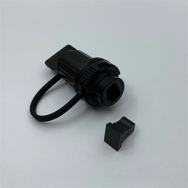
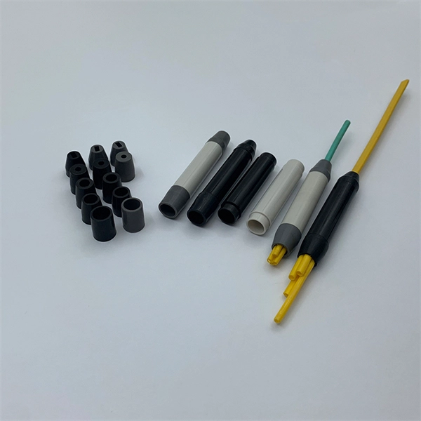
A variety of optical fiber connectors are available, but SC and LC connectors are the most common types of connectors on the market. Typical connectors are rated for 500–1,000 mating cycles. The main differences among types of connectors are dimensions and. An optical fiber connector is a device used to link optical fibers, facilitating the efficient transmission of light signals. They come in various types like SC, LC, ST, and MTP, each designed for specific. Fiber connector types LC, SC, FC, ST, MTP, and MPO are widely used in past and present. What are the differences between them? Who is the most popular one? Find the answer in the article. What is a Fiber Connector? The optical fiber connector is a kind of detachable passive optical component used. Fiber optic cable assembly quality hinges on selecting the right connector type—most commonly LC, SC, or ST—to match device ports and installation environment. When selecting the appropriate optical module for a network application, one crucial factor to consider is the type of fiber connector it employs. Fiber optic connectors are used to the mechanical and optical means for cross connecting fibers. There have been many types of connectors developed for fiber cable. With the demands of different application scenarios.
[PDF]
Joints between high-current bus sections often have precisely machined matching surfaces that are silver-plated to reduce contact resistance. At extra high voltages (more than 300 kV) in outdoor buses, corona discharge around the connections becomes a source of radio-frequency interference and power loss, so special connection fittings designed. OverviewIn , a busbar (also bus bar) is a metallic strip or bar, typically housed inside,, and for local high current power distribution, transmission, or switching s. The busbar's material composition and cross-sectional size determine the maximum current it can safely carry. Busbars can have a cross-sectional area of as little as 10 square millimetres (0.016 sq in), but. • – Data transfer channel connecting parts of a computer• – Low resistance electrical conductor for high current transmission and distribution• – Modular approach t.
[PDF]
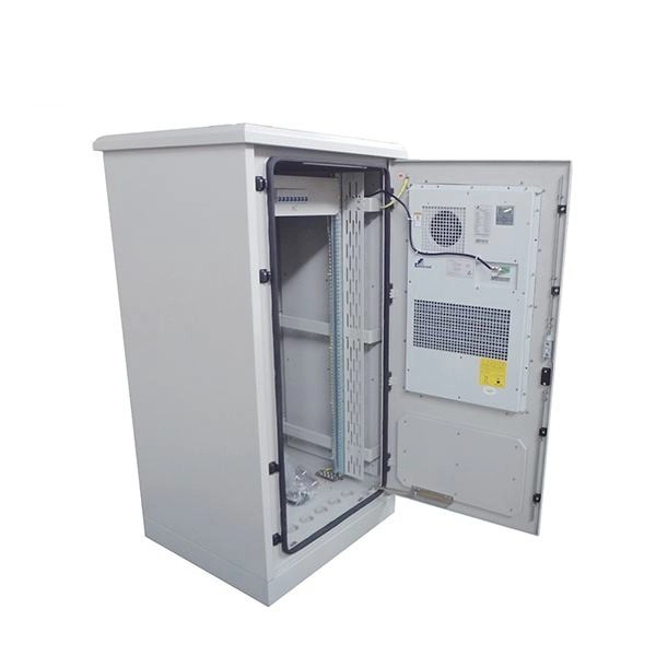
A distribution box, or DB box, is a circuit breaker enclosure. It is a vital part and central hub of any electrical system. The hub distributes electrical power from a single input source to various circuits throughout a building. Today, electrical systems are essential for homes and industries. But what exactly is a power distribution box, and why is it so essential in our daily lives? The DB panel board controls the flow of electricity. A distribution box, also known as a power distribution box or electrical distribution box, is used to distribute electrical power safely to multiple circuits. Distribution. Electrical systems power our homes, offices, and industrial facilities, but behind every reliable electrical setup lies a crucial component that often goes unnoticed: the distribution box. This essential piece of equipment serves as the nerve center of your electrical system, managing power flow. A power distribution box is a key part of any electrical system. Without it, managing power would be messy, unsafe, and inefficient. In this guide, we'll explain what a power. A distribution box is a vital piece of equipment that ensures the effective and safe distribution of electrical power in various parts within a building or complex. It is widely employed in residential, commercial and industrial set-ups for circuit control and protection. Understanding its significance.
[PDF]
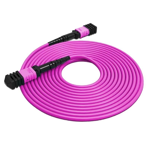
Several common cable outer sheath materials are PVC, PE, LSZH, AT and rodent-proof sheath materials. PVC is the most widely used fiber optic cable outer sheath material. What Is a Cable Sheath and Why It Matters 🔍 The cable sheath is the outer protective layer of a fiber optic cable. Its primary functions include: While the optical fiber itself remains largely unchanged, the sheath material determines how the cable behaves in fire scenarios, outdoor environments. The main function of the fiber cable outer sheath is to protect the optical fibers in the optical cable from external damage. At the same time, it must have. PVC vs LSZH vs TPU: Which sheath material for fiber optic cables in 2026? The jacket material determines the reliability, fire resistance, and lifespan of a fiber optic cable. At the same time, it must have. If so, then do remember that Fiber cables are made with high-grade glass cores and environmental protective sheaths, which can endure everything from residential network connections to underwater links. In this article, we'll discuss in detail the construction of Fiber optic cables and also see the. The sheath or outer sheath is the outermost protective layer in the optical cable structure, mainly made of PE sheath material and PVC sheath material, and halogen-free flame-retardant sheath material and electric tracking resistant sheath material are used in special occasions.
[PDF]
The vertical clearance for overhead fiber optic lines above the highway must be a minimum of 18 feet. The exception is ADSS cables which are approved for installation in the power space by qualified personnel. All aerial cables should be installed clear of any obstructions. The Fiber Optic Association, Inc. (FOA) was founded in 1995 to help develop the workforce to build the fiber optic networks to support a rapid expansion in communications and the Internet. The charter of the FOA was to promote professionalism in fiber optics through education, certification, and. The basic pole height is 7m and the tip diameter is 150mm. In case of special sections, crossing obstacles or roads or railways, the pole height of 8m, 9m, etc. can be selected according to the actual terrain. If the surface is stone, the depth needs to be 0. 9m, and if the surface is other soil. Generally a 12 inch to 24 inch soil separation is recommended as a safety barrier and for locating purposes. 9938 | SuperiorEssexCommunications. com Page 1 of 4 TECHNICAL GUIDELINE July 30, 2020 TG030 Rev. FIBER is used for relocating any fiber optic cable from one location to another. Field conditions will vary, so the actual location. to n utral comm.
[PDF]
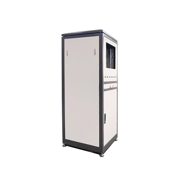
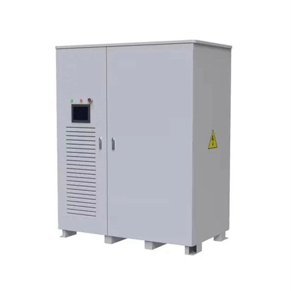
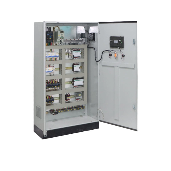
Marker balls, also known as aerial marker balls or power line marker balls, are brightly colored spherical objects attached to overhead power lines. These balls are made of durable, light materials like plastic or rubber. As a key electrical equipment for receiving and distributing high-voltage electric energy in the power system, the high-voltage distribution cabinet plays an indispensable role in the safe and stable operation of the power system. There are many types of components in the cabinet, and each has a. A distribution box is a key part of electrical systems in buildings. It helps control and distribute electricity to different areas. Inside, you'll find parts like circuit breakers and fuses that protect the system from problems like overloads and short circuits. Today, electrical systems are essential for homes and industries. But what exactly is a power distribution box, and why is it so essential in our daily lives? The DB panel board controls the flow of electricity. In a substation there are numbers of incoming and outgoing circuits each having its isolator, circuit breaker, transformers etc. connected to bus-bar system. These equipment are mostly static.
[PDF]
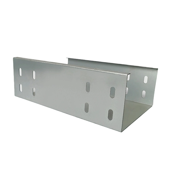
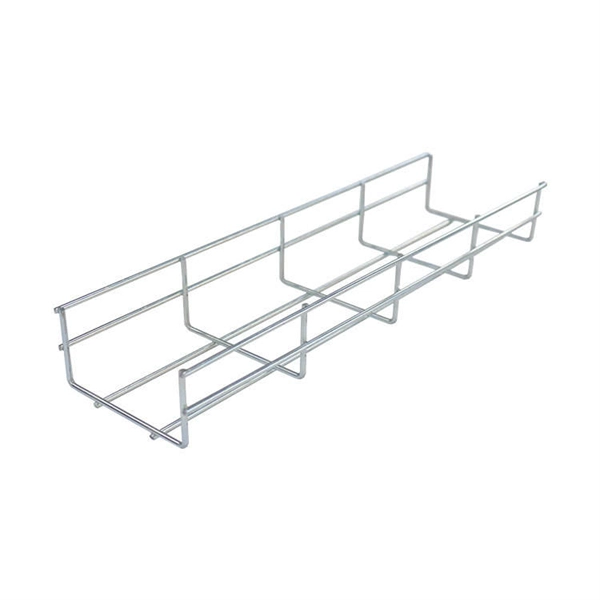
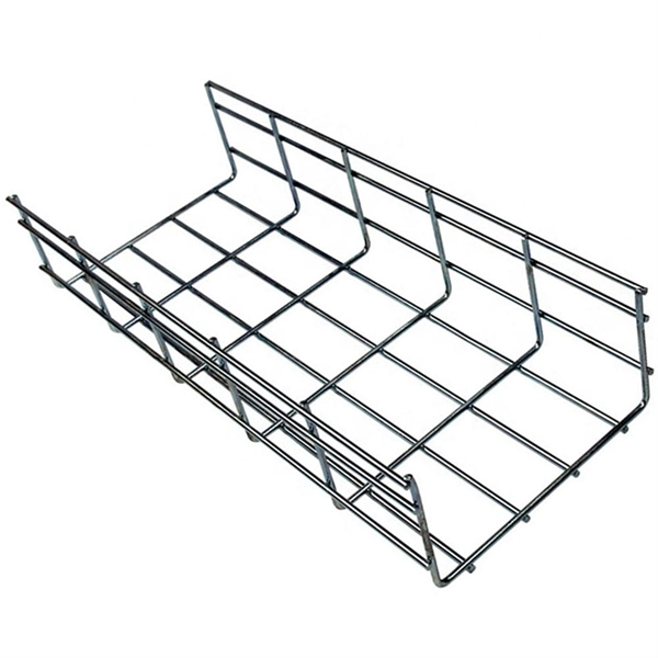
Our customers can count us for buying Electrical Cable Tray, Ladder Cable Tray, PVC Cable Tray, Mild Steel Cable Tray, Perforated Cable Tray, Raceway, Stainless Steel Cable Tray In Niger. We have our exceptional range designed and. Brilltech Engineers Pvt. brings the Cable Trays in Niger just for you! We, one of the well-known Cable Trays Manufacturers in Niger, offer top-notch trays that keep your electrical system organized and protected. Our durable, high-quality trays come in various sizes and styles to fit any. Looking for a trusted source to buy Cable Tray In Niger? Brilltech Engineers Pvt. Ltd is the one you can reach. We have a highly experienced team, well-loaded manufacturing unit and a lot more to match up the ever-evolving needs of our customers. Moreover, our focus on maintaining high quality and. Micro Sheet Crafts have been involved in offering a wide range of storing systems and solutions, as per the requirements of the customers. We offer Cable Tray in Niger in different specifications at competitive market prices. We believe in building fruitful business partnerships. Every buyer chooses us. Cable House has earned loads of appreciation in the market as one of the reputed manufacturers of Cable Tray in Niger.
[PDF]

Residual current devices (RCDs) at both the tertiary (equipment-level) and secondary (zone-level) stages. Ensures safe disconnection in case of faults or leakage currents. A distribution box is installed under the main distribution box, and a switch box is installed under the distribution box. These boxes feature bottom entry and exit cables, front-opening doors, and main busbars connected with copper strips for optimal contact. They also include metering systems, ensuring. In a newly constructed residential area, a 10kV power line is introduced into the substation. After stepping down the voltage through the transformer's low-voltage side (0. 4kV), power distribution is achieved through three levels of distribution boxes: the main distribution board, secondary. Equipment inside usually includes isolating switches, circuit breakers, and residual current devices (RCDs). Supplies power to specific buildings or floors. It is specially designed for the special situation of the project construction site and meets the relevant construction power specifications and standards of the. A distribution board (also known as panelboard, circuit breaker panel, breaker panel, circuit breaker, electric panel, fuse box or DB box) is a component of an electricity supply system that divides an electrical power feed into subsidiary circuits while providing a protective fuse or circuit.
[PDF]
39 A/mm² is safely below the typical 1. The busbar must survive the heat from a short-circuit fault. Use the IEC 60949 adiabatic formula: $S ge frac {I_k times sqrt {t}} {k}$. Since 1. Instead of using many separate wires, a busbar provides a single, organized path for carrying high current between different electrical components. Bus bars are the essential components in the electrical distribution systems (EDB) serving as primary conductors that carry current between 1). Circuit breakers, 2). Proper sizing is the essential for safety, efficiency and compliance with international electrical. Click Calculate to see the required area and recommended size. Full IEC Verification Enter your base parameters as in the standard method. This disables the safety factor and reveals IEC-specific inputs. Enter derating factors, short-circuit current. The Busbar Size Calculator helps engineers and electricians find the right copper or aluminum busbar dimensions based on current capacity, material type, and environmental conditions. The current rating is calculated from the conductor cross-sectional area, material (copper or aluminium), and maximum. A bus bar is a solid bar or metallic strip that is used for power distribution. Busbars have extensive use inside panel boards, busways, and switchgears. The busbars of right sizes ensure a safe and secure current distribution with ease and flexibility. We can consider a busbar as a node or a group.
[PDF]
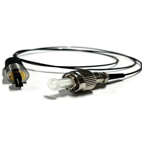
An optical power meter (OPM) works by converting light energy into electrical energy using a photodiode sensor. When light from a fiber optic cable hits the sensor, it generates a small electrical current related to the light's strength. Optical power meters are a key element in the optimization and maintenance of such optical networks and of their components. In this article, learn: What is an optical power meter? An optical power meter (OPM) measures the power levels of light signals in devices that transmit data or power using. An optical power meter (OPM) is a device used to measure the power in an optical signal. The term usually refers to a device for testing average power in fiber optic systems. It measures the optical power transmitted through a fiber, helping to verify if the light signal is strong enough for communication. Beginners may find it complex, but understanding its function makes it. This article provides a comprehensive overview of optical power meters, instruments used to measure the power of light beams. It details the main components, including sensor heads and display units, and explains the two primary sensor technologies: robust thermal sensors for high powers and. A fiber-optic power meter is a quantitative measurement instrument, not a diagnostic tool by itself.
[PDF]
A fiber optic transceiver (also called an optical transceiver) is a compact module that both transmits and receives data signals through optical fibers. It serves a dual purpose — transmitting electrical signals as light pulses and receiving light pulses to convert them back into. Fiber optic communication systems use light pulses to transmit information over long distances via optical fibers. These systems rely on three vital components working together – the communication channel, the optical transmitter, and the optical receiver. The optical fiber cable itself makes up. They consist of a transmitter on one end of a fiber and a receiver on the other end. Most systems operate by transmitting in one direction on one fiber and in the reverse direction on another fiber for full duplex operation. Most systems use a "transceiver" which includes both transmission and. A fiber optic cable consists of five basic components: the core, the cladding, the coating, the strengthening fibers, and the cable jacket. Fiber optics deals with study of propagation of light through transparent dielectric wageguides. The fiber optics are used for transmission of data from point to point location. Such fibers are widely used in fiber-optic communication, where they permit transmission over longer distances and at higher bandwidths (data transfer rates) than.
[PDF]
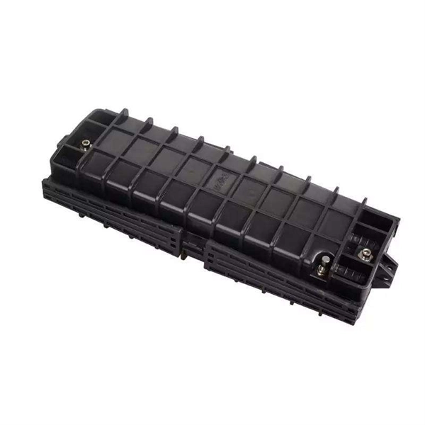
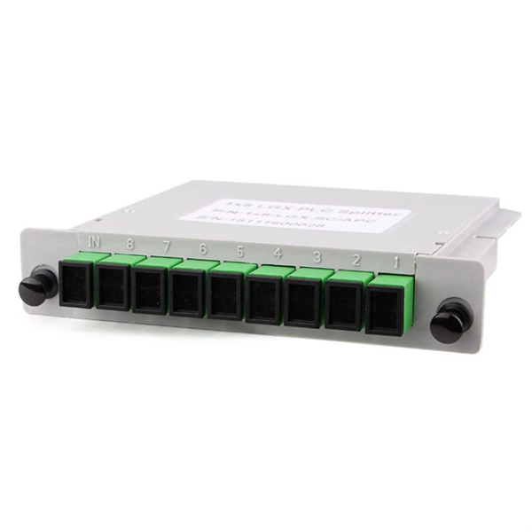
The centralized splitter approach typically uses a 1×32 splitter in an outside plant (OSP) enclosure, such as a fiber distribution terminal. The 1×32 splitter is directly connected via a single fiber to an OLT in the central office. They are typically installed in each optical network between the PON OLT (optical line terminal) and ONTs (optical network terminals) that the OLT serves. Generally, two kinds of fiber optic splitters are popular, which are FBT splitters and PLC splitters. The differences between the two have been. A fiber broadband provider typically determines and overall split ratio for the network, such as 1x32 or 1x64, and uses combinations of splitters to meet that ratio with each PON port. 1x32 splits were common in North America for G-PON architectures. As XGS-PON continues to be adopted, some service. This comprehensive guide explains how optical splitters work, what types are available, and how to select the optical splitter best buy or optical cable splitter best buy for your network deployment. What Is a Fiber Optic Splitter? A fiber optic splitter is a passive optical component designed to. Star couplers are used for their uniform splitting, while WDM splitters are used to split light beams of different wavelengths. Application Areas Fiber optic splitters are used in various areas, including active optical networks, passive optical networks, FTTX access networks, and measurement.
[PDF]
Picking up the best router for fiber internet isn't just about going to the market and choosing one of the best wireless routers. Instead, you need to carefully look at its specs, performance, and the type of securit.
[PDF]
Overview: The VCS HUB8 is a speaker distribution hub that mounts in a structured wiring cabinet or on the wall. It connects between the speaker-level output of an amplifier or receiver and the Niles volume controls, allowing you to adjust the sound level of each pair of speakers. Removable. Open box: An item in excellent, new condition with no wear. The item may be missing the original. Tube kits consist of reflectors and bracket assemblies, tube assemblies (5- and 10-foot straight tubes, L-tubes, and U-tubes as requ andards Association (CSA) for outdoor or non-residential indoor spaces. Standard heaters are. Amazon. com Return Policy: Amazon. com Voluntary 30-Day Return Guarantee: You can return many items you have purchased within 30 days following delivery of the item to you. You can find out more about the. The Synopsys VCS® functional verification solution is the primary verification solution used by a majority of the world's top semiconductor companies. VCS provides the industry's highest performance simulation and constraint solver engines. VCS' simulation engine natively takes full advantage of. If a VCS hardware component contains covered software that is executed by its primary processing unit, does that make all software-based components on that primary processing unit covered software, simply because it physically resides on the same unit? What is VCS and VCS hardware? What does.
[PDF]