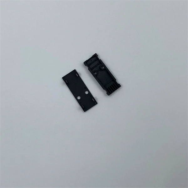
These modules are engineered with high-grade components designed to withstand the vibrations of washboard forest service roads and the temperature swings of high-altitude passes. 00 Original price was: $46. Activates High current relay when High Beams are turned on, used to add large light bars and driving lights without having to install additional switches in the dash. Plugs directly into Polaris Pulse System for switch lighting and keyed on ignition. The CanM8 Cannect Duo (Speed Pulse & High Beam) Interface is a 2-output CAN Bus interface which provides a quick solution for detecting high beam activity on vehicles which feature CAN Bus wiring. The Cannect Duo Interface also features a square pulsed speed signal output from the vehicle at a. Electronic technology has advanced so that an electronic control unit (ECU) is required to control the functions of full LED automotive headlights. An ECU consists of mainly LED drivers for headlight functions such as high beams, low beams, daytime running lights, position lights, turn indicators. This module resolves the issues with the headlight turning off, or flashing after the ignition is turned on. This issue is mainly affecting Chrysler, Jeep, Dodge vehicles, but some other modern cars will have this same issue. They offer a true plug-and-play experience, effectively eliminating the common flickering issues associated with.
[PDF]
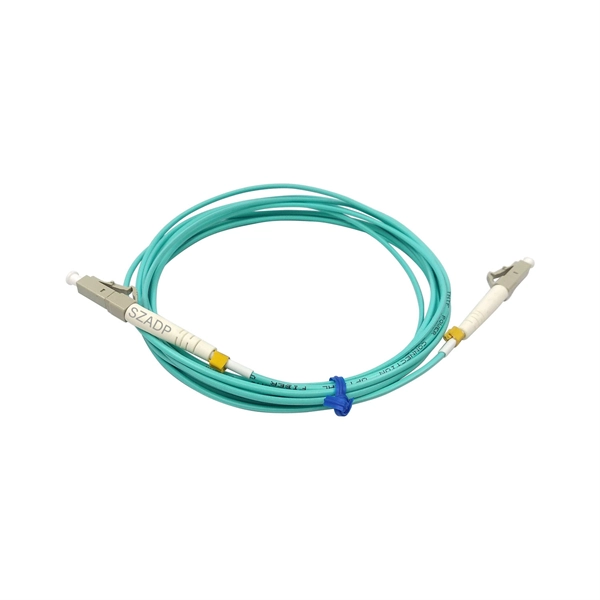
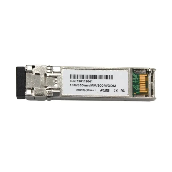
It supports multi-mode fiber with a reach of 300m via a duplex LC connector. Designed for extended temperatures (-40°C to 85°C), it includes Digital Optical Monitoring (DOM) and guarantees full compatibility with H3C equipment, making it ideal for harsh environment deployments. Optical modules transmit signals over optical fibers. Optical transmission features low loss and is fit for long distance transmission. The. Max. Note: Due to DigiKey value-add services the packaging type may change when product is purchased at quantities beneath the standard package. Buy now, ships today. SFP-XG-SX-MM850-D-C - Transceiver Module Networking and Communications 10Gbps 850nm LC Duplex Pluggable, SFP+ from ATGBICS. View. This H3C® SFP-XG-SX-MM850-A compatible SFP+ transceiver provides 10GBase-SR throughput up to 300m over multi-mode fiber (MMF) using a wavelength of 850nm via an LC connector. Our transceiver is built to meet or exceed OEM specifications and is guaranteed to be 100% compatible with H3C®. With a data rate of 10. This transceiver is compliant with SFF-8431, SFF-8432 and IEEE 802. 3ae standards and for seamless interoperability in multivendor environments.
[PDF]
Joints between high-current bus sections often have precisely machined matching surfaces that are silver-plated to reduce contact resistance. At extra high voltages (more than 300 kV) in outdoor buses, corona discharge around the connections becomes a source of radio-frequency interference and power loss, so special connection fittings designed. OverviewIn , a busbar (also bus bar) is a metallic strip or bar, typically housed inside,, and for local high current power distribution, transmission, or switching s. The busbar's material composition and cross-sectional size determine the maximum current it can safely carry. Busbars can have a cross-sectional area of as little as 10 square millimetres (0.016 sq in), but. • – Data transfer channel connecting parts of a computer• – Low resistance electrical conductor for high current transmission and distribution• – Modular approach t.
[PDF]
Description: Explore how optical modules enable high-speed data conversion across data centers, 5G networks, storage systems, and WDM applications. Learn about SFP, SFP28, CWDM, and DWDM solutions. Optical modules are widely used in various industries. Aerech Networks will use this article to introduce you to the application scenarios of optical modules. Optical modules are critical components in modern data communication, serving to convert electrical. Optical module is mainly used in the field of data communication. Its function is to realize the mutual conversion of photoelectric signals. Due to the rise of big data, blockchain, cloud computing, Internet of things, artificial intelligence and 5G, data traffic has increased rapidly. As the demand for faster and more reliable internet and data services grows, understanding these devices becomes increasingly important. This guide will explore. What You'll Learn in This Guide By reading this article, you will: By the end, you'll have a clear, expert-level understanding of CFP optical modules—and more importantly, the confidence to decide whether they are the right fit for your specific application.
[PDF]
Underground fiber optic cable installation follows specific standards that govern burial depth, testing methods, installation techniques, and safety requirements. Underground cables are pulled in conduit that is buried underground, usually 1-1. 2 meters (3-4 feet) deep to reduce the likelihood of accidentally being dug up. In extreme cold climates, cables may need to be buried at greater depths where there temperatures are colder and frost penetrates to. The Fiber Optic Association, Inc. (FOA) was founded in 1995 to help develop the workforce to build the fiber optic networks to support a rapid expansion in communications and the Internet. The charter of the FOA was to promote professionalism in fiber optics through education, certification, and. This guide walks through each stage of underground fiber installation—from route planning and conduit selection to splicing, termination, and testing—to help ensure long-term network performance and reliability. These standards, established by organizations like the National Electrical Code (NEC), National Electrical Safety Code (NESC), and. Installing underground fiber optic cables is critical to establishing high speed internet infrastructure that delivers reliable connectivity for businesses nationwide. Unlike traditional copper systems, fiber optic cables require specialized handling techniques and precise installation methods to.
[PDF]
As illustrated in typical SFP internal structure diagrams, the module's core components include an optical transmitter assembly (TOSA), laser driver, optical receiver assembly (ROSA)—some high-sensitivity modules (like L16. 2) use APD receivers, which require an additional booster. As a key element in optical communication systems, optical transceivers serve as media between network devices to transmit and receive data. There has been lots of articles and guides on transceiver modules in the perspective of the package type while only a few of them cover the internal elements. Optical modules are devices used to connect network devices, transmit and receive data between network devices, and can be used to convert optical and electrical signals. The optical module is a very important component in an optical communication system. When you remove the metal housing of the optical transceiver, you will find that the internal components are connected to each other. The following section will focus on. In the era of 5G, AI, and high-speed data centers, optical modules serve as the core bridge for converting electrical signals to optical signals (and vice versa), enabling fast, reliable data transmission across networks. Among various optical module form factors, SFP (Small Form-Factor Pluggable). The optical transceiver module is mainly composed of three parts: housing, optical device and integrated circuit board. The following section will focus on.
[PDF]
At present, key breakthroughs in optical fiber communication technology include high-order modulation formats, polarization multiplexing, wavelength division multiplexing, etc. Optical fiber communication can be widely applied in the fields of the internet and telephone networks . With the rapid development of cloud computing, big data, the Internet of Things, and other new technologies, we have entered an era of digitalization and informatization. The number of internet users has been steadily increasing, which has accelerated the exponential expansion of data services. A. Then the different technologies in optical fiber communication along with their features are discussed briefly.
[PDF]
Several common cable outer sheath materials are PVC, PE, LSZH, AT and rodent-proof sheath materials. PVC is the most widely used fiber optic cable outer sheath material. What Is a Cable Sheath and Why It Matters 🔍 The cable sheath is the outer protective layer of a fiber optic cable. Its primary functions include: While the optical fiber itself remains largely unchanged, the sheath material determines how the cable behaves in fire scenarios, outdoor environments. The main function of the fiber cable outer sheath is to protect the optical fibers in the optical cable from external damage. At the same time, it must have. PVC vs LSZH vs TPU: Which sheath material for fiber optic cables in 2026? The jacket material determines the reliability, fire resistance, and lifespan of a fiber optic cable. At the same time, it must have. If so, then do remember that Fiber cables are made with high-grade glass cores and environmental protective sheaths, which can endure everything from residential network connections to underwater links. In this article, we'll discuss in detail the construction of Fiber optic cables and also see the. The sheath or outer sheath is the outermost protective layer in the optical cable structure, mainly made of PE sheath material and PVC sheath material, and halogen-free flame-retardant sheath material and electric tracking resistant sheath material are used in special occasions.
[PDF]
The vertical clearance for overhead fiber optic lines above the highway must be a minimum of 18 feet. The exception is ADSS cables which are approved for installation in the power space by qualified personnel. All aerial cables should be installed clear of any obstructions. The Fiber Optic Association, Inc. (FOA) was founded in 1995 to help develop the workforce to build the fiber optic networks to support a rapid expansion in communications and the Internet. The charter of the FOA was to promote professionalism in fiber optics through education, certification, and. The basic pole height is 7m and the tip diameter is 150mm. In case of special sections, crossing obstacles or roads or railways, the pole height of 8m, 9m, etc. can be selected according to the actual terrain. If the surface is stone, the depth needs to be 0. 9m, and if the surface is other soil. Generally a 12 inch to 24 inch soil separation is recommended as a safety barrier and for locating purposes. 9938 | SuperiorEssexCommunications. com Page 1 of 4 TECHNICAL GUIDELINE July 30, 2020 TG030 Rev. FIBER is used for relocating any fiber optic cable from one location to another. Field conditions will vary, so the actual location. to n utral comm.
[PDF]
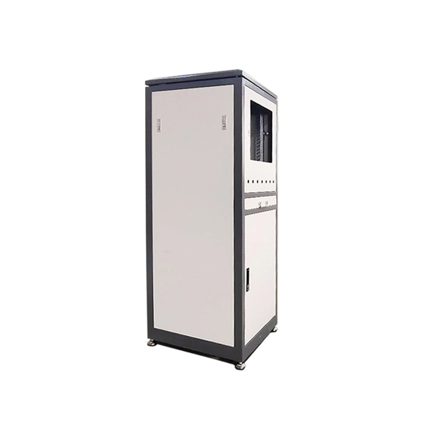
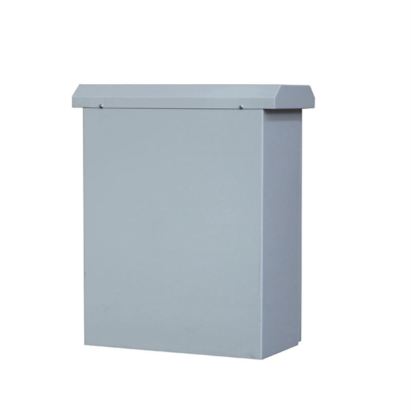
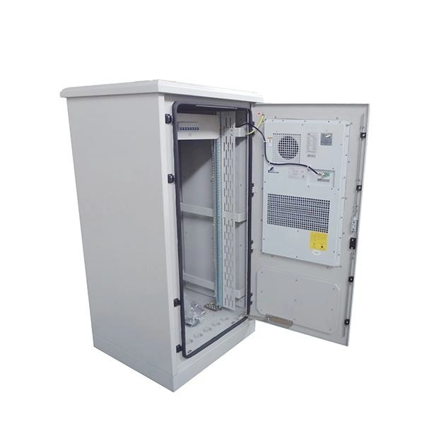
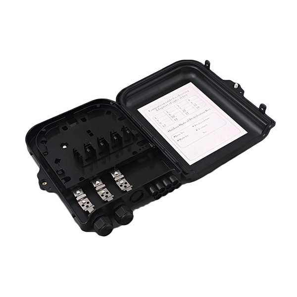
Marker balls, also known as aerial marker balls or power line marker balls, are brightly colored spherical objects attached to overhead power lines. These balls are made of durable, light materials like plastic or rubber. As a key electrical equipment for receiving and distributing high-voltage electric energy in the power system, the high-voltage distribution cabinet plays an indispensable role in the safe and stable operation of the power system. There are many types of components in the cabinet, and each has a. A distribution box is a key part of electrical systems in buildings. It helps control and distribute electricity to different areas. Inside, you'll find parts like circuit breakers and fuses that protect the system from problems like overloads and short circuits. Today, electrical systems are essential for homes and industries. But what exactly is a power distribution box, and why is it so essential in our daily lives? The DB panel board controls the flow of electricity. In a substation there are numbers of incoming and outgoing circuits each having its isolator, circuit breaker, transformers etc. connected to bus-bar system. These equipment are mostly static.
[PDF]
These characteristics make DST splitters suitable for optical benches and reference measurement systems, where lasers with low to medium power are split into multiple beams with minimal loss. DST beam splitters are designed for unpolarized light sources. A beam splitter or beamsplitter is an optical device that splits a beam of light into a transmitted and a reflected beam. It is a crucial part of many optical experimental and measurement systems, such as interferometers, also finding widespread application in fibre optic telecommunications. Beamsplitters are often classified according to their construction: cube or plate. Signal attenuation refers to the reduction in the intensity of a light beam as it passes through a medium or a device. When a beam splitter divides the incoming light. The Keysight Technology, Inc. family of high-performance beamsplitters offers industry-leading polarization and beam control with low wavefront distortion. For more than 35 years, Keysight has designed and produced beamsplitters exclusively for the most demanding custom interferometry applications. Cube beamsplitters avoid beam displacement by working at 0° angle of incidence and placing the coated surface between two right angle prisms, but power handling can be limited if epoxy is used to bond the prisms. Newport offers a wide variety of Beamsplitters in various shapes.
[PDF]
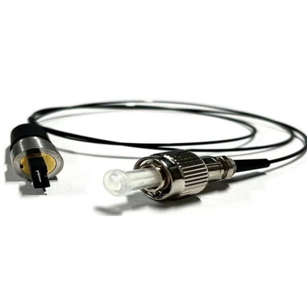
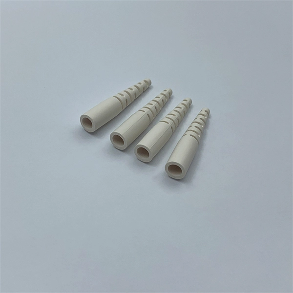
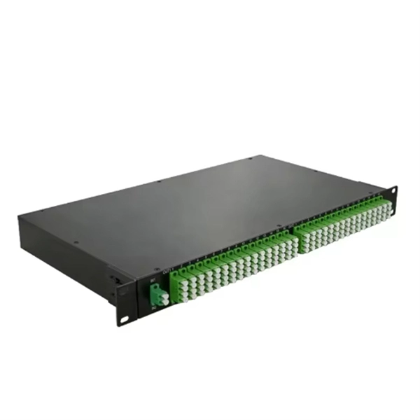
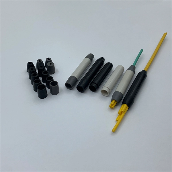
Fiber optic pigtails are roughly divided into two categories: Multimode and single-mode fiber pigtails. Multimode pigtails consist of 62. 5 or 50-core multimode fiber optic cables that are terminated with multimode connectors. To classify them further, they can be subdivided into OM1. This guide covers everything: what fiber optic pigtails are, how they differ from patch cords, which connector and polish type to specify, how to choose between mechanical and fusion splicing, and the real-world applications where pigtails are the right call. Whether you're building out an ODF. A fiber optic pigtail is a short length of optical fiber —typically 0. 5m to 2m—that has a factory-terminated connector on one end and bare fiber on the other end. The connector end is polished and tested under factory conditions, ensuring low insertion loss and high return loss. The bare fiber end. Understanding the different models and characteristics of fiber pigtails can help users better match system requirements in practical applications and ensure efficient and stable fiber optic communications. The connector end can be linked directly to network equipment, while the exposed end can be spliced to another fiber optic cable. In this comprehensive guide, we explore the different types of fiber optic pigtails available, including MU, LC, SC, FC, DIN, APC, and UPC.
[PDF]
The V-groove substrate is the heart of the Fiber Array, providing precise alignment for the optical fibers. This substrate, typically made from silicon, glass, or ceramic, features a series of V-shaped grooves etched with sub-micron accuracy. Fiber Array (FA for short) is an array formed by installing a bundle of optical fibers or a fiber ribbon on the substrate at specified intervals by using a V-Groove (V-Groove) substrate. Fiber optic arrays in optical communications mainly include a substrate, a platen, and an optical fiber. Whether integrated into planar lightwave circuits (PLCs), optical switches, or high-speed transceivers, FAs play a vital role in ensuring. What is a Fiber Array (FA)? A Fiber Array, commonly abbreviated as FA, is a critical interface component in Silicon Photonics (SiPh) packaging, Photonic Integrated Circuits (PIC), and Co-Packaged Optics (CPO) architectures. It is responsible for efficiently coupling "external optical fibers" with. Fiber Arrays (FAs), as high-precision, high-performance optical components, have become indispensable core elements in fields such as optical communications, photonic integration, and laser processing. Typically, such an array is formed only for the very end of the fibre bundle, rather than over the entire length of the.
[PDF]
This section provides an overview for fiber optic sensors as well as their applications and principles. Also, please take a look at the list of 18 fiber optic sensor manufacturers and their company ranki.
[PDF]
39 A/mm² is safely below the typical 1. The busbar must survive the heat from a short-circuit fault. Use the IEC 60949 adiabatic formula: $S ge frac {I_k times sqrt {t}} {k}$. Since 1. Instead of using many separate wires, a busbar provides a single, organized path for carrying high current between different electrical components. Bus bars are the essential components in the electrical distribution systems (EDB) serving as primary conductors that carry current between 1). Circuit breakers, 2). Proper sizing is the essential for safety, efficiency and compliance with international electrical. Click Calculate to see the required area and recommended size. Full IEC Verification Enter your base parameters as in the standard method. This disables the safety factor and reveals IEC-specific inputs. Enter derating factors, short-circuit current. The Busbar Size Calculator helps engineers and electricians find the right copper or aluminum busbar dimensions based on current capacity, material type, and environmental conditions. The current rating is calculated from the conductor cross-sectional area, material (copper or aluminium), and maximum. A bus bar is a solid bar or metallic strip that is used for power distribution. Busbars have extensive use inside panel boards, busways, and switchgears. The busbars of right sizes ensure a safe and secure current distribution with ease and flexibility. We can consider a busbar as a node or a group.
[PDF]