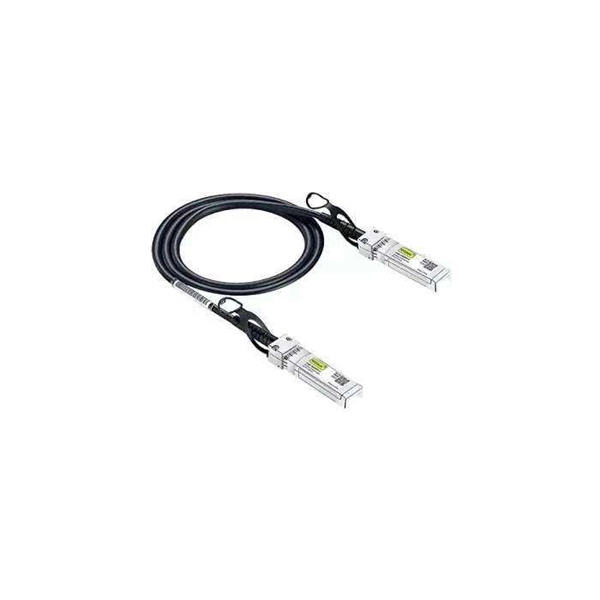
EIA/TIA 568 B allows any fiber optic connector as long as it has a FOCIS (Fiber Optic Connector Intermateability Standard) document behind it. Fiber optic cold connection, also known as mechanical splicing, is a widely used method of connecting optical fibers in a network. Unlike fusion splicing, which uses heat to join two optical fibers together, cold connection uses mechanical means to create a stable and low-loss connection. Unlike fiber splicing, which is permanent, connectors allow for easy connection and disconnection of cables, making them ideal for maintenance and flexibility in. Fiber optic joints or terminations are made two ways: 1) splices which create a permanent joint between the two fibers or 2) connectors that mate two fibers to create a temporary joint and/or connect the fiber to a piece of network gear. These terminations must be of the right style, installed in a. Fiber termination refers to the process of preparing the end of a fiber optic cable to connect to another fiber, a device, or a network. Proper termination is essential for ensuring optimal performance, reducing signal loss, and maintaining the durability of the connection. Since the introduction of fiber optic technology decades ago, a variety of connector types have been.
[PDF]
There are currently three methods of looking inside a fiber optic connector: (1) Non-destructive X-ray (2) Lossless sonar (3) Destructive cross section These methods help engineers determine the causes and effects of fiber optic connector failures and monitor the connector assembly. There are currently three methods of looking inside a fiber optic connector: (1) Non-destructive X-ray (2) Lossless sonar (3) Destructive cross section These methods help engineers determine the causes and effects of fiber optic connector failures and monitor the connector assembly. Fiber Optic Center offers a unique cross-sectioning service to identify and isolate problems related to fiber optic terminations that would otherwise be invisible. All. There are two major uses for visual inspection of fiber optic connectors. Video microscopes should have ability to record images and some may have ability to analyze connector condition to standards. Look for dirt, contamination, scratches or any other problem. Since connectors are susceptible to damage that is not immediately obvious to the naked eye—the inspection phase is vital. When proceeding with the inspection of connectors, there are two main components to inspect: the connector itself and the ferrule. With the press of a single button, FOCIS Flex auto-focuses, captures and centers the end-face image, applies Pass/Fail rules, displays image and Pass/Fail results, saves results internally and/or wirelessly transfers data to a.
[PDF]
This paper proposes a mathematical model for busbars used within a high current power supply. The obtained thermal model can be used to analyse the thermal behaviour of busbars in steady-state conditions at different values of the electric current, cross-section and length. Improving surface temperature measurement of the power cable and insulated busbar using the heat insulated layer Abstract The surface temperature measurement is susceptible to the surrounding air for the cable or the insulated busbar laid in free air. Therefore, an approach for improving their. The thermal analysis takes into account the heat conduction and convection of a copper busbar system used to supply a test bench with high currents in order to check the electro-thermal behaviour of power circuit breakers during overload and short circuit conditions. This paper proposes a. Current is supplied via bus bars or wire bonding in power supply lines for power electronics devices such as inverters. Because inverters and similar devices operate with PWM carrier frequencies of several kHz, high-frequency current flows in their bus bars. Influences from the skin effect cannot.
[PDF]
Using OptiSystem software, we evaluated AWG performance in both multiplexer (MUX) and demultiplexer (DEMUX) configurations within the C-band (1530-1565 nm), analyzing key parameters including insertion loss (1. 4 dB), channel crosstalk (-32±2 dB), polarization-dependent loss. Array waveguide gratings (AWGs) have been widely used in multi-purpose and multi-functional integrated photonic devices for Microwave photonics (MWP) systems. In this paper, we compare the effect of output waveguide configurations on the performance of AWGs. The AWG with an output waveguide. Arrayed waveguide gratings (AWGs) are key optical components of various new applications in telecommunication, astrology, medical imaging, and spectroscopy. This study presents a comprehensive performance analysis and design optimization of AWG-based. A high-performance silicon arrayed-waveguide grating (AWG) with 0. 4-nm channel spacing for dense wavelength-division multiplexing systems is designed and realized successfully. The device design involves broadening the arrayed waveguides far beyond the single-mode regime, which minimizes random.
[PDF]
1 × 8 and 1 × 16 traditional/saddle arrayed waveguide grating (AWG) devices with different core layer materials applied in fiber Bragg grating (FBG) system were designed, fabricated and compared. We ap.
[PDF]
Positive busbars, which collect all positive connections. Key Steps: When wiring a pair of 12V busbars, connect the positive terminal of each load to a stud on the positive busbar and their negative terminal to a stud on the negative busbar. 5' above batteries on inside of cockpit combing below decks. Install one new positive bus bar beside the negative one separated by about two inches 3. Positive and negative busbars are physically identical apart from the red/black colours used by some manufacturers to visually differentiate between. A Complete Guide to Battery Terminal Connector Types The store will not work correctly in the case when cookies are disabled. JavaScript seems to be disabled in your browser. For the best experience on our site, be sure to turn on Javascript in your browser. Skip to Content Blog Sign In Create an. This image illustrates a standard car battery with top post terminals and labeled connectors for the positive (+) and negative (–) ends, emphasizing safe and correct installation. A battery terminal connector is a fitting or clamp that attaches to a battery's terminal to connect a cable. In other. Both positive and negative terminals are the soul of the electrical system of the car, allowing the engine to start while keeping other components running. The catch? Mix-up or loose connection can cause electrical failure, drained batteries, and damage to wiring. This blog guides you how the two.
[PDF]
Join me in this concise video as I demonstrate the meticulous process of connecting stranded wires in a junction box through soldering. Whether you're a DIY enthusiast or a professional electrician, this brief tutorial offers valuable insights into using soldering for. I was changing a switch in my house when I found a number of connections in the electrical box that were soldered rather than secured with a wire nut. The solder joints look very well done, the conductors were twisted together nicely and the solder itself was nicely done. It was not some oxidized. I have found several soldered wires inside junction boxes in my older lake house. I see mostly neutrals this way with the hots going to outlets or switches where they are looped onto the screws. If I am upgrading the junction box to a larger one I just cut the. I don't know why anyone would do this now a days but thats the interesting thing about being an inspector. I inspected a house today that someone is wiring the old school way. The grounds he used wire nuts on. more Join me. Because of different characteristics of dissimilar metals, devices such as pressure terminal or pressure splicing connectors and soldering lugs shall be identified for the material of the conductor and shall be properly installed and used. No wiring systems of any.
[PDF]