The blue port on your AT&T Fiber equipment, typically found on the Optical Network Terminal (ONT), is the gateway for your high-speed internet connection. It's not just any port; it's a specialized fiber optic connector designed to receive and transmit data at incredible speeds. It supports both EPON and GPON technologies, providing robust internet connectivity with dual-band Wi-Fi (2. 4G and 5G), multiple Gigabit Ethernet (GE) ports, two USB ports, and a telephone (TEL). Your router has Wi-Fi 6 (802. 11ax) capabilities, which gets you up to 800 Mbps Wi-Fi speeds when using Wi-Fi 6-capable devices. Dual-band Wi-Fi Simultaneous dual band Wi-Fi, with 2. 4GHz (4x4) and 5GHz (4x4), automatically selects the best signal for your devices using band steering. In other words. This conversion happens either through an Optical Network Terminal (ONT) or directly via specialized router ports. Compatible router: Verify that your router supports fiber optic input (look for an SFP or WAN port labeled. The fiber optic cable does not plug directly into a standard home router because the signal type must be translated. This specialized equipment serves as the. Ultra-fast Wi-Fi Speeds: Up to 3 Gbps dual band Wi-Fi enables faster browsing, streaming, and downloading—all at the same time. Boosted Coverage: Four high-performance antennas and Beamforming technology combine to extend strong, reliable WiFi throughout your home. More Connections: OFDMA and.
[PDF]
They support devices like IP cameras, wireless access points, and IoT devices, enabling placement in remote areas without nearby power outlets, a capability that regular switches lack as they can only handle data transmission and require a separate PoE injector for power supply. Network switches form the backbone of any Local Area Network, or "LAN" (pronounced "lan") for short. On this page you will learn what differentiates a PoE enabled switch from a regular LAN switch, when you should use a PoE switch versus a PoE injector and, what exactly is PoE (Power over Ethernet). A PoE (Power over Ethernet) switch is a network switch that delivers both power and data through a single Ethernet cable to connected devices such as IP cameras, VoIP phones, wireless access points, and IoT devices. This eliminates the need for separate power adapters, reducing cable clutter and. In today's blog, we'll explain what a PoE switch is and how it powers devices through one Ethernet cable. We'll also look at the different types of PoE switches, their benefits, and how they can be used in real-world situations. What Is PoE (Power. PoE switches deliver power and data over Ethernet cables, eliminating the need for separate adapters. For businesses, this simplifies deployment of IP cameras, access points, and VoIP.
[PDF]
The number of core switch ports is large, usually modular, and can be freely matched with optical ports and Gigabit Ethernet ports. The general core switches are Layer 3 switches, and various advanced network protocols such as routing protocol/ACL/QoS/load balancing can. Does every network need a core switch? Can a router be used instead of a core switch? How do I determine the bandwidth requirements for my core switch? What security features should I look for in a core switch? How often should I update the firmware on my core switch? What are the key performance. Home / Ethernet Switch / Do I need a core switch? The simple answer is “yes. ” Every complex network comprises multiple computers and devices. To route the traffic and improve the performance of the network, you must have a proper mechanism. What would you employ to simplify the network? The core. ● Up to 28 native nonblocking 40/100 Gigabit Ethernet QSFP28 ports. 3-GHz x86 CPU with 8 cores and 32 GB of DDR4 memory. ● Up to 960 GB of SSD. rity to ensure guests and property peaceful and safe. Our solutions provide stable and continu arge commercial buildings host many separate entities. The primary function is to access user data or aggregate some switch data at the access layer. This kind of switch can configure Vlan simple routing protocol and some simple. The number of conventional switch ports is generally 24-48.
[PDF]
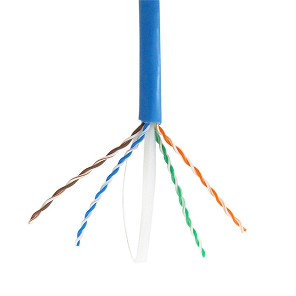
Connect the Ethernet cables: Connect one end of an Ethernet cable to the PoE switch's uplink port, and the other end to the network router or modem. Then, connect the devices that require power to the PoE ports on the switch using Ethernet cables. A Power over Ethernet (PoE) switch is a device that enables the transmission of both power and data over a single Ethernet cable. This eliminates the need for separate power cables and allows for flexible placement of network devices in locations where power outlets may be limited or absent. In. The first thing you need to do is connect your switch to an electrical outlet so it is powered on. This means you can power devices such as wireless access points, IP cameras, and VoIP phones using the same cable that provides network connectivity. 3at (PoE+), and. One of the biggest advantages of copper twisted pair Ethernet cable (also called Category cable) is it's ability to perform two critical functions at the same time: When these functions are simultaneously performed, it is known as PoE or Power over Ethernet. It utilizes efficient low-voltage 43 to 57 VDC over twisted-pair network cabling, such as Category 6A, Category 6, and Category 5e. This means PoE can be installed without risk to.
[PDF]
Fiber optic switches utilize specialized ports such as XFP, SFP, CFP, SFP+, or QSFP+ to connect to fiber optic cables. These ports aren't directly compatible with the cables themselves; they require transceiver modules. SFP/SFP+ Modules: Small Form-factor Pluggable (SFP) modules are transceivers that connect the switch to the fiber optic cables. The choice between SFP and SFP+ depends on the network speed requirements, with SFP+ supporting higher speeds (up to 10 Gbps). Fiber Optic Patch Panels: These are used to. Choose an SFP module based on the fiber optic cabling that will be connected to the network switches. Always integrate duplex (two strand) fiber optic cabling or higher strand counts. The process requires understanding the type of fiber optic port on your switch and selecting the appropriate transceiver module. Always. I wish to connect (single mode) fibre optic cable to Fibre optic switch ( DIN-rail mounted) directly without using patchl panel or patch cords. I would also like to know what precautions should be taken during cable terminations. This is due to no or less space available for patch panels in my. The process of connecting fiber optic cables to network switches involves meticulous attention to detail and adherence to industry best practices to ensure reliable data transmission and seamless network connectivity. Before commencing the connection process, it is essential to ascertain the.
[PDF]
Port aggregation allows you to group multiple physical ports into one unit. Port aggregation is useful for implementing load balancing and provides a redundant link backup. By aggregating. All UniFi Switches support aggregation, except USW-Flex, USW-Flex-Mini and USW-Ultra. Port aggregation is not supported on most UniFi Gateways; it is only supported on the EFG, UXG Enterprise, UDM Pro, UDM SE and UDM Pro Max. Because of this, you should not aggregate two ports connected from a. In computer networking, link aggregation is the combining (aggregating) of multiple network connections in parallel by any of several methods. Link aggregation increases total bandwidth beyond what a single connection could sustain, and provides redundancy where all but one of the physical links. A Link Aggregation Group (LAG) optimizes the usage of switch ports by linking a group of ports to form a single, logical, higher-bandwidth link. Aggregating ports multiply the bandwidth and increase port flexibility for Sophos Switch. Network administrators typically use this technique to increase backbone capacity between switches or to support high-speed data pipelines for servers. By establishing a.
[PDF]
Insert a compatible SFP transceiver into the converter's port, making sure it matches the network's media type and speed. Then, connect one end of the fiber cable to the transceiver and the other to the appropriate port on a switch, router, or another media converter. Fiber media converters translate copper's electrical signals into fiber's optical signals, and back again. This allows networks to extend beyond the 100 m copper limit while gaining higher bandwidth and resistance to electromagnetic interference. In the illustrated setup, each LAN links to a. A fiber media converter is a networking device that allows you to convert a signal from one medium to another. This allows you to connect devices that use different types of cabling, such as a computer. While fiber optic ports are becoming increasingly common on networked electronics, the majority of connected devices still rely on RJ45 twisted pair connections. To help bridge the copper-fiber divide, media converters and transceiver modules (also known as SFPs or mini-GBICs) are often required. Use Fiber Media Converter in Your Network Media converters today are widely deployed in all. It is a device used to convert fiber optic cables to Ethernet cables to provide better connectivity. It is necessary to convert fiber optic signals to Ethernet signals because many network devices can only communicate with Ethernet signals. Fiber optic cables are known for the unmatched speed.
[PDF]
Resolving these issues involves steps like checking cable connections, soft resets, updating firmware, and specific solutions for different router brands like ASUS and Spectrum. It often indicates that something is wrong with your internet connection or the device itself. Fortunately, diagnosing and resolving these issues doesn't have to be complicated. In this comprehensive guide, we will walk you through the common causes of a red light on your router and provide. A router showing a red light can mean different things, like a service outage, misconfiguration, or loose connection, all of which can lead to a broken internet connection. Fortunately, there are heaps of ways to fix a red blinking light on your router. One of the first things you should try is to. Turn off the router and disconnect the power cord. Check that the PON cable is free from damage or sprains. Even if you have the best router, you may experience a loss of connection or other issues and see that dreaded red light. When it's green and steady, everything is fine. However, when it blinks red or stays solid red, it signifies a Loss of Signal, a problem preventing your router from communicating.
[PDF]
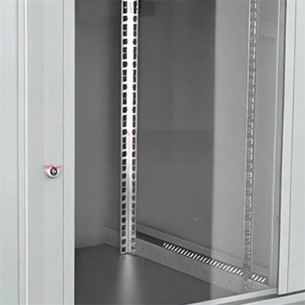
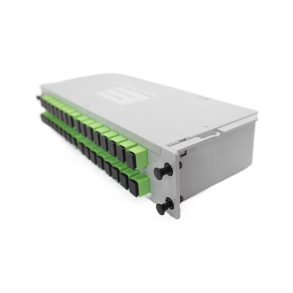
Find reliable fiber ODF with price from top suppliers. Shop our collection of high-quality patch panels and distribution frames for communication networks. Optical Distribution Frame (ODF) is integrated components in any fiber management system to handle termination and cross-connection of cables. Pre-terminated ODFs with cables are pre-installed with connectors and cable for quick and easy installation. Units with pre-terminated cables offer. Streamline your fiber connectivity with our premium Fiber Optic Patch Panels and ODF systems. Designed for reliability and ease of use, our rack-mount and wall-mount solutions provide the perfect environment for splicing, terminating, and managing your critical fiber optic connections. It is a device that splices, distributes, and splits optical fibers and provides protection and management of optical fibers. Growth is driven by investments in hyperscale data centers and fiber-to-the-x (FTTx) networks. Asia-Pacific remains the manufacturing and consumption hub, with significant activity also in North America and Europe. Innovation is reshaping product offerings and, consequently, pricing tiers.
[PDF]
While there are situations when you will have to route cable through structural members such as studs, joists, and rafters, the job is much easier if you can run the cable along the surfaces of these frames. When you have a situation where you need to run cable through. Running new wiring within existing, finished walls of a wood-framed structure is a common necessity for home upgrades, whether for installing low-voltage data and audio cables or for extending line-voltage electrical circuits. Another is to conceal the cords and cables within the walls. This guide will help you learn how to run low voltage cables through the wall using low voltage boxes and face plates. To learn how to add. Many home improvement projects require you to install new electrical cables inside finished walls. The process is often called "snaking" or "fishing," with good reason. Cables often must be bent, slithered and coaxed around stud spaces and through small holes in the framing. Click on any image to see a larger version. When installing an electrical box, drill a hole in the floor between the studs on the same side as the electrical box. Staple down the wire right above the hole and. Method One: In order to cut the panel correctly, you first need to make the right measurements. Mark this distance on the panel you will be using. Make sure to mark this from the top.
[PDF]
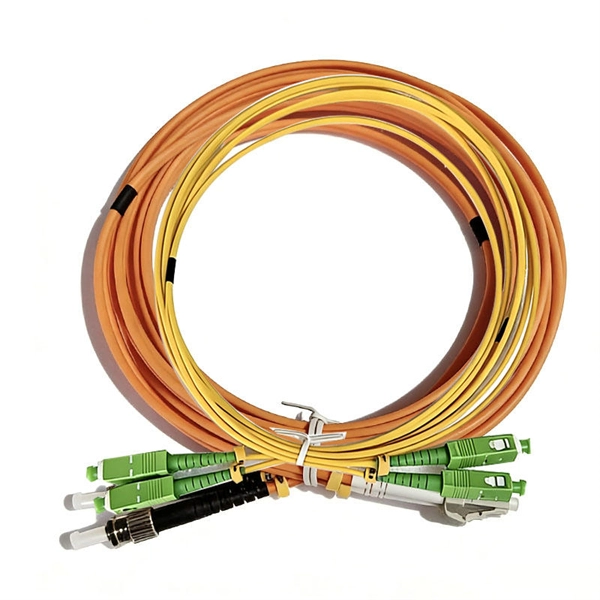
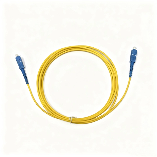
To check a fiber connection, connect a jumper to the optical source port and the other end to an optical meter. Press the “test” or “signal” button to send a signal from the source to the meter. While there are many different fiber optic cable tests, the most common version is an insertion loss test, also known as an attenuation, jumper, or connectivity test. This test requires a special testing kit and protective eyewear, but it will help you diagnose problems with the cable's. We'll explain why it's vital to test fiber optic cables, the three most popular methods, and when you should use them. Related: Fiber Optic Connectors – Identification Guide Regularly testing fiber optic cables helps minimize network downtime, lengthens the network's longevity, reduces maintenance. In this guide, we'll explore effective methods to check your fiber connection, including tools required and common issues to look out for. Below is an in-depth guide on how to assess the health and performance of a fiber optic connection: Before relying on technical tools, start. Whether you're a professional or a DIY enthusiast, knowing how to test fiber optic cables is crucial. In this blog, we'll explore different methods, including using a flashlight, advanced tools like Fluke testers, and more cost-effective options for testing fiber optics. In fiber optic communication, data is transmitted over two strands of fiber: one for.
[PDF]
ODF, Splitter Distribution Box, and Fiber Terminal Box are not interchangeable, but complementary components of an FTTH network. ODF ensures efficient backbone fiber management in central offices. In FTTH, FTTB, and other fiber access networks, terms such as Fiber Optic Termination Box, Fiber Distribution Box (FDB), and ODF (Optical Distribution Frame) are frequently mentioned. Although all three are related to fiber connection and management, their installation locations, functional roles. To realize the connection of fiber optic cable, we often need to use ODF (optical distribution frame), fiber optic termination box ( rack mount fiber optic patch panel, fiber outlet), fiber distribution box for fiber management in the fiber optic link. Although they all belong to the optical distribution and management system, their. An Optical Distribution Frame (ODF) is a dedicated unit designed to organize, terminate, and interconnect fiber optic cables. It brings together fiber splicing, patching, and cable routing in a single structure, while shielding sensitive connectors and splices from mechanical stress or. Although both appear to "manage fiber," they serve very different roles in a modern optical network. This 2026 expert guide explains the functions, placement, structure, and application scenarios of ODFs and fiber patch panels-and includes a deep engineering FAQ that resolves real-world deployment.
[PDF]
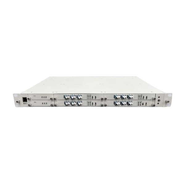
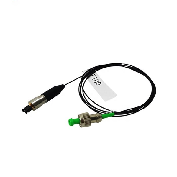
The operating principle of an OCS is similar to telephone circuit switching. When two ports need to communicate, the controller configures a path in the optical switch matrix, using optical components to route the optical signal from one fiber to another, forming an independent. Optical switching represents a fundamental technological evolution, shifting data routing from the domain of electrons to the realm of photons, or light. This transition allows data to remain in its native optical form as it travels through fiber optic networks, eliminating the need for. Optical switches are devices that route light signals from one path to another without converting them into electrical signals first. They're a core component in fiber-optic networks, where data travels as pulses of light through glass fibers. Every time that light needs to change direction or jump. Optical switches, a key component in modern network infrastructure, are devices used in optical fiber networks for signal management. Unlike traditional electrical switches, which transmit data as electrical signals, optical switches handle data transmission in the form of light. These devices play a critical role in modern optical networks by enabling dynamic reconfiguration, wavelength routing, and protection switching. In this article, we will explore the fundamentals of optical switches, their types, and their applications in various fields. An optical switch is a.
[PDF]
To connect a fiber, align the optical connector with the optical port and gently insert the optical fiber into the port. A fiber adapter (also called a flange) is a fiber connection component. An active optical cable (AOC) is a fixed-length optical fiber with optical modules at both ends. It can be directly connected to an optical port on a device. Table 10-3 lists the models and attributes of. Optical modules are widely used in switches, network interface cards (NICs), routers, and other communication devices. During use, reading optical module information helps understand its real-time operating status, enabling faster troubleshooting of link abnormalities. Solution: To solve this problem, you can follow these steps: Check if the fiber and optical modules are compatible. Perform a. All other trademarks and trade names mentioned in this document are the property of their respective holders. The purchased products, services and features are stipulated by the contract made between Huawei and the customer. Major causes of the interface physically down event include hardware and software failures. Hardware failures: include hardware. Step 1: Antistatic strap must be worn to prevent static damage. Step 2: Take out the optical module, ring and label up, the gold finger is facing down, Note that the right and the negative can not be reversed.
[PDF]
This complete guide explores everything you need to know about ODFs — from their structure, types, and key components, to installation best practices and modern design trends. Whether you're building a central office, data center, or FTTx distribution network, understanding the right ODF. In modern data centers and enterprise networks, Optical Distribution Frames (ODF) serve as the backbone for organizing, terminating, and managing fiber optic connections. This article explores the types, components, applications, installation, and maintenance best practices, providing a. An Optical Distribution Frame (ODF) is the central hub for fiber splicing, termination, patching, and cable protection in modern optical networks. As data centers, enterprises, telecom operators, and smart-building infrastructures deploy increasingly dense fiber links, ODFs provide the structured. Achieve successful cable management, handle high amounts of fiber cable and add density to fiber frames with the new DCX Optical Distribution Frame (ODF) System which features innovations like flippable cassettes, modular frame design and multiple configuration options. The ODF System Components. Optical distribution frames (ODFs) are an all-important network element at the heart of a fiber network. They provide efficient fiber optic management, connectivity, and protection.
[PDF]