In this tutorial, we will learn how to use the DHT11 sensor module with the Micro: bit V2 board. This sensor can measure temperature and humidity; we'll display these measurements on an LCD screen. Also, I have used the Microsoft MakeCode platform to write our code. Welcome to the class on making a temperature and humidity detection device! This project uses a micro:bit board, OLED display, and temperature-humidity sensor connected via the IIC interface of the Petal Base Expansion Board to achieve real-time detection and display of environmental temperature. In this tutorial, we will learn how to use the DHT11 sensor module with the Micro: bit V2 board. MakeCode is great because it. Imagine monitoring real-time temperature, humidity levels, atmospheric pressure, rainfall detection, air quality index (AQI), and more—right from your local network. With the power of the Arduino UNO R4 WiFi, you can create a dynamic weather dashboard web page that displays all your environmental. This project is a smart weather station built using the ESP8266 microcontroller integrated with multiple environmental sensors — BMP180 for pressure and altitude, DHT11 for temperature and humidity, and MQ135 for air quality monitoring. It continuously collects real-time weather data and air. This tutorial is all about Humidity & Temperature Monitoring with DHT11 & STM32 Microcontroller. There is a dht module that comes with the MicroPython firmware by default.
[PDF]
If your ISP doesn't require a technician to set up your connection, these are the steps to self-install fiber internet: Locate your fiber network terminal. Connect the fiber terminal to the network box. Connect your device to the network. Self-install is pretty straightforward--it's similar to getting a new tv, game console, tablet or computer out of the box and setting it up on your own. If you (or someone in your home) are comfortable with that, you'll be able to install and set up your TDS service. However, there are a couple of. The service box (Optical Network Terminal/ ONT) brings AT&T Internet into your home. Once you locate it (may be in basement, utility closet or garage), remove cover and connect: GREEN fiber connector to GREEN PON port (if not already connected). Post-installation optimization matters —proper router placement, firmware updates, and network security configuration maximize your fiber internet investment. 65% of. Whether you go for an indoor or outdoor installation can impact your internet's reliability, speed and even how easy it is to troubleshoot issues. Let's break it all down, so you can make an informed choice and get the most out of your fiber experience. To install your broadband, you only need to understand a few basic steps. Most DSL services provide a modem, router, filters, cables, and self-installation manual. If you have a home phone, connect the.
[PDF]
Full Technical Specifications: Explore our complete range of directional and dual directional couplers, featuring ultra-wideband operation from 0. This catalog details models with coupling values from 5 dB to 50 dB and power ratings up to 500 Watts. How does 6W market outlook report help businesses in making decisions? 6W monitors the market across 60+ countries Globally, publishing an annual market outlook report that analyses trends, key drivers, Size, Volume, Revenue, opportunities, and market segments. This report offers comprehensive. IPP's directional couplers offer some of the widest bandwidths at the highest power levels in the industry. These directional couplers are available in frequencies from 1 MHz., in power. Directional couplers are critical components in radio frequency (RF) and microwave systems, used to split or combine signals while maintaining signal integrity. These passive devices allow a signal to be directed from one port to another, with a portion of the signal being coupled to an auxiliary. We are an RF / Microwave / Wireless Telecom Manufacturer for component, modules and systems. We offer the widest range and best performance RF Directional Couplers and Quadrature Hybrids in the world, extremely aggressive pricing structure. RF directional couplers often. CorechTEK's Directional Couplers are engineered for precise RF and Microwave signal monitoring and power sampling. CorechTEK Couplers.
[PDF]
This guide details the necessary physical and digital steps to connect your fiber line and activate your internet service. The fiber optic cable does not plug directly into a standard home router because the signal type must be translated. Why Use Fiber Optic Internet? Before diving into the setup, let's quickly recap why fiber optics are worth the effort: Lightning-fast speeds (up to 1 Gbps or higher). Low latency for. Most fiber ISPs, including Mercury, provide an ONT that connects directly to your router via an Ethernet cable. This means you don't need a specialized modem-router device, but your router must support high-speed Ethernet input. While many users ask if fiber internet needs a modem, it actually. The process to connect fiber optic cable to router requires careful attention to detail, but I'll walk you through every critical step with the precision and clarity you deserve. This comprehensive guide combines industry standards with field-tested practices to ensure you achieve a rock-solid. Setting up a fiber internet connection requires understanding key hardware components and following a specific connection sequence to establish your home network. See you soon! 🚀 How to connect a fiber optic. Fiber optic internet is generally installed in the following 5 steps, which we'll dive deeper into throughout the article: A technician checks your area and prepares the connection from the neighborhood fiber network.
[PDF]
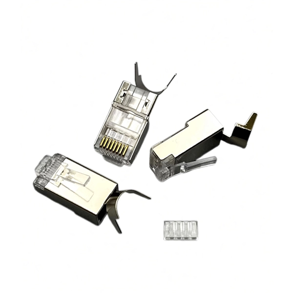
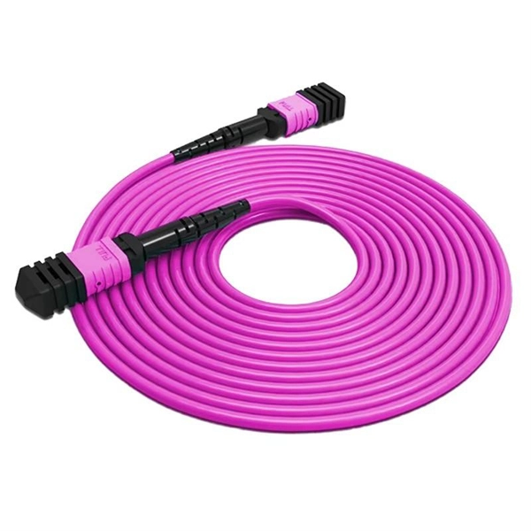
Connecting a multi-mode SFP to single-mode fiber creates a major signal mismatch. A small portion of the transmitted light gets captured. This leads to high attenuation and frequent link drops. I suggest you avoid such setups. Use them if essential and with proper mode conditioning. But what happens when you need to connect an existing multi-mode campus network to a new single-mode service provider link? You can't just splice them together. This is where fiber conversion comes in. This guide will break down the professional methods to achieve seamless single-mode to multi-mode. A fiber optic cable or optical fiber cable is a medium used for transmitting optical signals from one place to another. It consists of a strand of glass fibers inside an insulated casing. Fiber optic cable comprises a core, cladding, and a buffer. I've seen people use a single-mode. But not all fiber cables are created equal: multimode (MM) and single mode (SM) fibers are the two primary types, each engineered for specific use cases, from short-range data center connections to transcontinental telecom backbones. This type of patch cord helps to transfer the single mode signal into a multimode signal by aligning the two different types of fibers. However, it's important to note that this method may have. Multimode fiber cabling is used for indoor, short distance applications and single-mode fiber cabling is used for outdoor, long distance application.
[PDF]
The most common operating principle of a directional fiber coupler is evanescent wave coupling in a configuration where two fiber cores come close to each other. Such a device can be made by heating two bare fibers such that the glass begins to melt and the fibers fuse together. The tutorial has the following parts: Figure 1: A 2-by-2 fiber coupler. When using fiber optics, one often needs to use fiber. Fiber optic couplers, also known as fiber optic splitters, are devices used to split or combine optical signals in fiber optic networks. They play a crucial role in various applications, such as telecommunications, data centers, and fiber-to-the-home (FTTH) installations. In simple terms, they serve as the 'traffic managers' of the light that carries information within the fiber optic network. It functions by dividing a single incoming light path into multiple outgoing paths, or by combining light from several input paths into a single output fiber. This capability is fundamental. This tab provides a brief explanation of how we determine several key specifications for our 1x2 couplers. 1x2 couplers are manufactured using the same process as our 2x2 fiber optic couplers, except the second input port is internally terminated using a proprietary method that minimizes back.
[PDF]
In this article, you will learn the step-by-step process of testing your solar panels using a multimeter. We will cover the essential tools you need, the specific measurements to take, and how to interpret the results. By the end of this guide, you will be equipped with the knowledge to diagnose. Solar panels are usually tested under standard conditions using a light source that mimics the light from the sun on a clear day. You can use the following method if you want to test your solar panel under standard conditions. Testing solar panels is easy with a multimeter! To test the current. Your multimeter is your best friend when testing solar panels. You can use it to check: Here's how: Multimeter — I recommend getting one that is auto-ranging. Also, a simple voltmeter won't work here. You need a multimeter that can measure both volts and amps. Locate the open circuit voltage. Learning to test a solar panel with a multimeter is an investment in your knowledge and ability to manage your own solar energy system or provide valuable services in the growing solar industry. Measure Voc (open circuit voltage) — if it reads 0V, the panel or wiring is dead. If it reads 60–80 % of rated, a bypass diode has failed. Perfect for DIY solar builders, RV owners, o. more Audio tracks for some languages.
[PDF]
Using a multimeter, check continuity between the black connector and the marked pin of the optocoupler input that is not working. If there is no continuity, the possible causes are: Connect a 5 V to 24 V signal to the input being tested. Measure the voltage at the marked. Using a multimeter, you can perform several tests to assess the functionality of an optocoupler. Each test targets a specific aspect of the optocoupler's operation. An optocoupler is an essential electronic component that transfers signals without a direct electrical connection. more n this video, you will learn how to test an optocoupler (optoisolator) using a. Optocoupler is one type of ICs, It isolates input and output section by using optical technology this feature increase safety of circuit. Optocoupler has many part number, different part number has different output type so before checking it has to use part number to research with datasheet and. If any optically isolated input on the controller is not working, follow the steps below to identify the cause. For our demo purposes, we will be using the PC817, a commonly used transistor output optocoupler in electronics. An opto-isolator contains a source (emitter) of light, almost always a near infrared light-emitting diode (LED), that converts electrical input signal into light, a closed optical channel (also called dielectrical channel, and a photo sensor, which detects incoming light and either generates.
[PDF]
It works on the principle of sensing residual current which is why it is called a residual current device. Nowadays, all domestic and commercial electrical systems and circuits use RCDs. Today, we will see how you can connect an RCD to the distribution . Hey, in this article we are going to see the RCD Wiring diagram and its connection procedure. RCD means Residual Current Device. It is an electrical protective device that protects electrical circuits and devices from some electrical faults such as leakage faults, electrical shock, current. Distribution board is a safe system designed for house or building that included protective devices, isolator switches, circuit breaker and fuses to connect safely the cables and wires to the sub circuits and final sub circuits including their associated Live (Phase) Neutral and Earth conductors. Residual-current devices, commonly referred to as RCDs, are used in many practical applications. They can be found in fuse boxes, electrical switchgears or industrial machine control systems. Therefore. A distribution box uses MCBs, RCDs, and busbars to protect circuits, prevent shocks, and ensure safe power distribution in homes and buildings. This box keeps your home or building safe from electrical dangers. Devices that operate with electricity can cause leakage due to various reasons. If this leakage is not detected and cut off in time, it can lead to.
[PDF]
A beam splitter reflects some of the infrared light and lets the rest pass through. This creates two separate paths, which later overlap and interfere. This interference holds information about the light's wavelengths. The detector then turns this into usable data. Beamsplitters are optical components used to split incident light at a designated ratio into two separate beams. Additionally, beamsplitters can be used in reverse to combine two different beams into a single one. Beamsplitters are often classified according to their construction: cube or plate. Explore the precision, applications, and design principles of beam splitters, essential for advancements in scientific research and technology. Their precision and versatility make them. Two components really drive this process: the beam splitter and the detector. It's sensitive to both intensity and frequency. Together, they decide just how accurately an instrument. A beam splitter (or beamsplitter, power splitter) is an optical device which can split an incident light beam (e. a laser beam) into two (or sometimes more) beams, which may or may not have the same optical power (radiant flux). It is a crucial part of many optical experimental and measurement systems, such as interferometers, also finding widespread application in fibre optic telecommunications. In this blog, we will explore the.
[PDF]