In this tutorial, we will learn how to use the DHT11 sensor module with the Micro: bit V2 board. This sensor can measure temperature and humidity; we'll display these measurements on an LCD screen. Also, I have used the Microsoft MakeCode platform to write our code. Welcome to the class on making a temperature and humidity detection device! This project uses a micro:bit board, OLED display, and temperature-humidity sensor connected via the IIC interface of the Petal Base Expansion Board to achieve real-time detection and display of environmental temperature. In this tutorial, we will learn how to use the DHT11 sensor module with the Micro: bit V2 board. MakeCode is great because it. Imagine monitoring real-time temperature, humidity levels, atmospheric pressure, rainfall detection, air quality index (AQI), and more—right from your local network. With the power of the Arduino UNO R4 WiFi, you can create a dynamic weather dashboard web page that displays all your environmental. This project is a smart weather station built using the ESP8266 microcontroller integrated with multiple environmental sensors — BMP180 for pressure and altitude, DHT11 for temperature and humidity, and MQ135 for air quality monitoring. It continuously collects real-time weather data and air. This tutorial is all about Humidity & Temperature Monitoring with DHT11 & STM32 Microcontroller. There is a dht module that comes with the MicroPython firmware by default.
[PDF]

A beam splitter reflects some of the infrared light and lets the rest pass through. This creates two separate paths, which later overlap and interfere. This interference holds information about the light's wavelengths. The detector then turns this into usable data. Beamsplitters are optical components used to split incident light at a designated ratio into two separate beams. Additionally, beamsplitters can be used in reverse to combine two different beams into a single one. Beamsplitters are often classified according to their construction: cube or plate. Explore the precision, applications, and design principles of beam splitters, essential for advancements in scientific research and technology. Their precision and versatility make them. Two components really drive this process: the beam splitter and the detector. It's sensitive to both intensity and frequency. Together, they decide just how accurately an instrument. A beam splitter (or beamsplitter, power splitter) is an optical device which can split an incident light beam (e. a laser beam) into two (or sometimes more) beams, which may or may not have the same optical power (radiant flux). It is a crucial part of many optical experimental and measurement systems, such as interferometers, also finding widespread application in fibre optic telecommunications. In this blog, we will explore the.
[PDF]
While WDM offers many advantages, it also has some drawbacks: Signal Separation: Signals must be sufficiently spaced apart in frequency to avoid interference. Limited to Point-to-Point Circuits: Light waves carrying WDM signals are typically restricted to two-point connections. WDM stands for Wavelength Division Multiplexing. It's an optical multiplexing technique that utilizes different frequencies at varying wavelengths to transmit data independently over multiple channels. It is a technique in which signals of different wavelength are multiplexed together in order to get transmitted over an optical link. The concept of WDM was arrived in 1970. Wavelength division multiplexing (WDM) uses optical multiplexing to increase the bandwidth of existing fiber optic cables without adding additional cables. Optical. Wavelength Division Multiplexing (WDM) is a technology that has played a crucial role in the evolution and advancement of telecommunications and networking systems. It is designed to maximize the capacity of fiber-optic cables by simultaneously transmitting multiple data signals on the same fiber. This paper presents an overview about WDM technology and recent developments in this field and how the overall capacity of the communication network can be incremented using this technology. Keywords – bandwidth, multiplexing, optical network unit, OCDM, passive optical network., colors) of laser light. This technique enables bidirectional communications over a.
[PDF]
It enables uniform, shadow-free lighting by directing light along the same optical axis as the lens. When integrated into specialised lenses, the beam splitter divides the incoming light into two paths: one beam illuminates the object, while the other is used for image capture. Beamsplitters are fundamental components in optical engineering, serving to precisely divide a single input beam of light into two distinct output beams. This division allows for the simultaneous analysis or utilization of the light's properties along two separate paths. Additionally, beamsplitters can be used in reverse to combine two different beams into a single one. In practice, the reflective layer absorbs some light. It is a crucial part of many optical experimental and measurement systems. A cube beam splitter is, at its essence, an optical device that splits an incoming light beam into two sections. What are beamsplitters and how are they used in optics and photonics applications ? Beamsplitters are optical components that are used to. The beam splitter splits and then recombines infrared radiation, while the detector picks up the resulting signal. It's sensitive to both intensity and frequency. Together, they decide just how accurately an instrument captures those unique infrared “fingerprints” from different substances.
[PDF]
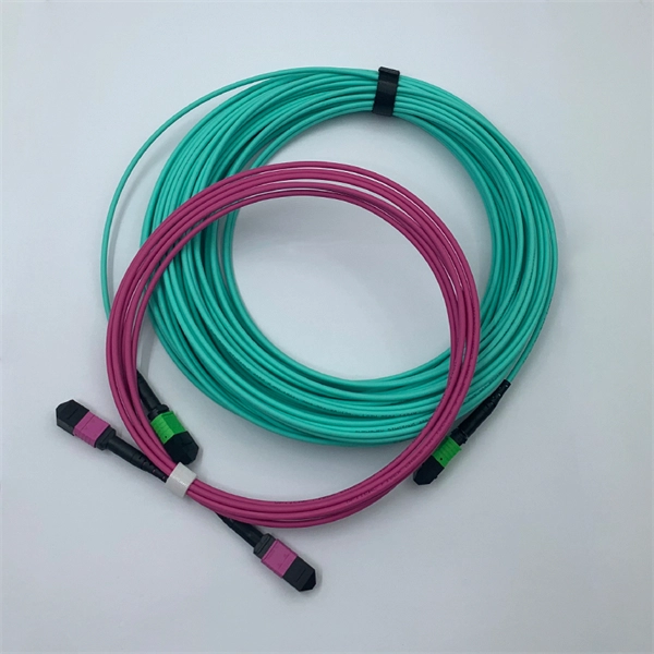
Connecting a multi-mode SFP to single-mode fiber creates a major signal mismatch. A small portion of the transmitted light gets captured. This leads to high attenuation and frequent link drops. I suggest you avoid such setups. Use them if essential and with proper mode conditioning. But what happens when you need to connect an existing multi-mode campus network to a new single-mode service provider link? You can't just splice them together. This is where fiber conversion comes in. This guide will break down the professional methods to achieve seamless single-mode to multi-mode. A fiber optic cable or optical fiber cable is a medium used for transmitting optical signals from one place to another. It consists of a strand of glass fibers inside an insulated casing. Fiber optic cable comprises a core, cladding, and a buffer. I've seen people use a single-mode. But not all fiber cables are created equal: multimode (MM) and single mode (SM) fibers are the two primary types, each engineered for specific use cases, from short-range data center connections to transcontinental telecom backbones. This type of patch cord helps to transfer the single mode signal into a multimode signal by aligning the two different types of fibers. However, it's important to note that this method may have. Multimode fiber cabling is used for indoor, short distance applications and single-mode fiber cabling is used for outdoor, long distance application.
[PDF]
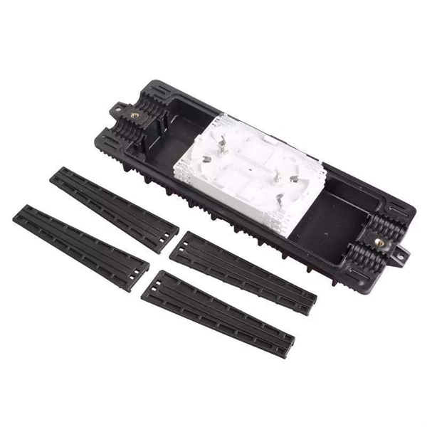
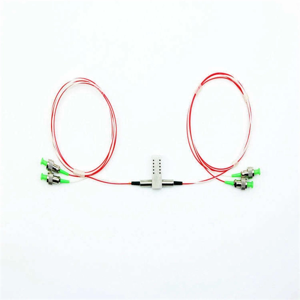
Use pigtails when connecting multiple wires to a single terminal, upgrading outlets or switches, or managing crowded electrical boxes. Pigtails play a crucial role in ensuring safe and efficient connections within electrical systems, especially when dealing with multiple wires or limited space. Understanding what a pigtail is and how it works can make your wiring projects smoother and safer. ” This method is especially useful when connecting wires to devices such as switches, outlets, and junction boxes, allowing. Proper using pigtails breaks this chain. By creating independent pathways, technicians isolate problems without shutting down complete circuits. Commercial buildings using this method report 83% faster troubleshooting times. The National Electrical Code mandates continuous neutral connections in. Optical fiber pigtails are short optical fibers used to connect fiber optics with other equipment (such as optical modules, splitters, etc. ), typically used in fiber optic networks. With advantages such as low insertion loss, high return loss, good interchangeability, and repeated plugging. A pigtail in electrical wiring is a short length of conductor used to transition from a bundle of multiple circuit wires to a single termination point, such as a device terminal or fixture connection. This technique is often employed when three or more wires need to be joined, ensuring that the.
[PDF]
In this article, you will learn the step-by-step process of testing your solar panels using a multimeter. We will cover the essential tools you need, the specific measurements to take, and how to interpret the results. By the end of this guide, you will be equipped with the knowledge to diagnose. Solar panels are usually tested under standard conditions using a light source that mimics the light from the sun on a clear day. You can use the following method if you want to test your solar panel under standard conditions. Testing solar panels is easy with a multimeter! To test the current. Your multimeter is your best friend when testing solar panels. You can use it to check: Here's how: Multimeter — I recommend getting one that is auto-ranging. Also, a simple voltmeter won't work here. You need a multimeter that can measure both volts and amps. Locate the open circuit voltage. Learning to test a solar panel with a multimeter is an investment in your knowledge and ability to manage your own solar energy system or provide valuable services in the growing solar industry. Measure Voc (open circuit voltage) — if it reads 0V, the panel or wiring is dead. If it reads 60–80 % of rated, a bypass diode has failed. Perfect for DIY solar builders, RV owners, o. more Audio tracks for some languages.
[PDF]
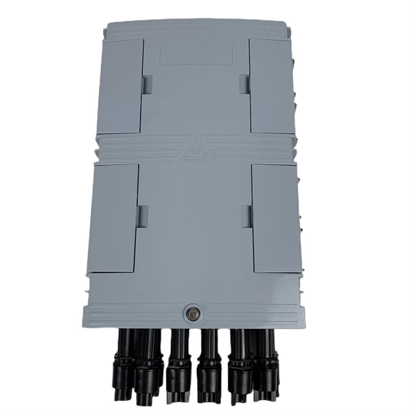
Explosion-proof electrical distribution boxes are essential for safety in hazardous environments. These specialized enclosures are built to contain internal explosions and stop the ignition of flammable materials. In this article, we will explore three key aspects:. Explosion-proof enclosures are used by such facilities to ensure the safe housing of electrical components that could cause a spark and ignite these gases in the atmosphere. What Is An Explosion Proof Box or Enclosure? They are a cast aluminum or iron box that can withstand a heavy-duty explosion. The Code of Federal Regulations (CFR) is the official legal print publication containing the codification of the general and permanent rules published in the Federal Register by the departments and agencies of the Federal Government. In this blog post, MINMILE, as high quality explosion proof control boxes manufacturer, will share the importance of explosion proof distribution boxes in. For electricians, engineers, and safety managers working in petrochemical plants, refineries, and manufacturing facilities, selecting the right explosion proof junction box ensures compliance, reliability, and peace of mind. Need Certified Explosion-Proof Junction Boxes? Get ATEX/IECEx options for.
[PDF]
Yes, you can connect two routers to one fiber modem, but understanding the 'how' and 'why' is crucial for optimal network performance. This guide clarifies the possibilities, practical methods, and potential pitfalls, ensuring you maximize your home or small office network. SFP (Small Form-factor Pluggable) is a compact, hot-pluggable network interface module used to connect network devices (switches, routers, firewalls) to fiber optic or copper cables. Think of it as the “translator” for your network equipment, converting electrical signals into optical signals. I'm planning to use a TP-Link MC220L transceiver to convert the optical signal to ethernet. This ethernet will then go through a 1 Gbit/s switch, and rout two ethernet cables to each floor. Can I Connect Two. The number of fiber cores is mainly related to the device interface of the fiber connection and the communication mode of the device. Generally speaking, the number of optical cores in an optical fiber is the total number of device interfaces multiplied by 2, plus 10% to 20% of the spare number., 100G, 50G), enabling flexible bandwidth utilization and cost-effective upgrades.
[PDF]

It works on the principle of sensing residual current which is why it is called a residual current device. Nowadays, all domestic and commercial electrical systems and circuits use RCDs. Today, we will see how you can connect an RCD to the distribution . Hey, in this article we are going to see the RCD Wiring diagram and its connection procedure. RCD means Residual Current Device. It is an electrical protective device that protects electrical circuits and devices from some electrical faults such as leakage faults, electrical shock, current. Distribution board is a safe system designed for house or building that included protective devices, isolator switches, circuit breaker and fuses to connect safely the cables and wires to the sub circuits and final sub circuits including their associated Live (Phase) Neutral and Earth conductors. Residual-current devices, commonly referred to as RCDs, are used in many practical applications. They can be found in fuse boxes, electrical switchgears or industrial machine control systems. Therefore. A distribution box uses MCBs, RCDs, and busbars to protect circuits, prevent shocks, and ensure safe power distribution in homes and buildings. This box keeps your home or building safe from electrical dangers. Devices that operate with electricity can cause leakage due to various reasons. If this leakage is not detected and cut off in time, it can lead to.
[PDF]
A spectrophotometer measures how much light a sample absorbs, helping you find chemical concentrations easily and accurately. Proper setup, calibration, and sample preparation are essential to get reliable and consistent results from your spectrophotometer. Widely used across scientific, medical, and industrial fields, it provides information about material composition and properties. This tool is essential for both. Spectrophotometry is an experimental technique that is used to measure the concentration of solutes in a specific solution by calculating the amount of light absorbed by those solutes. This technique is powerful because certain compounds will absorb different wavelengths of light at different. A spectrophotometer lets you measure how much light a sample absorbs at a certain wavelength. When you use spectrophotometry, you gain skills that help in many science fields. This guide makes spectroscopy simple by showing you how to use teaching tools and real experiments. In gen chem 1 we studied atomic line spectra, (section 6. We can therefore use spectra—the detailed patterns of colors—to figure out things like exactly.
[PDF]
Join me in this concise video as I demonstrate the meticulous process of connecting stranded wires in a junction box through soldering. Whether you're a DIY enthusiast or a professional electrician, this brief tutorial offers valuable insights into using soldering for. I was changing a switch in my house when I found a number of connections in the electrical box that were soldered rather than secured with a wire nut. The solder joints look very well done, the conductors were twisted together nicely and the solder itself was nicely done. It was not some oxidized. I have found several soldered wires inside junction boxes in my older lake house. I see mostly neutrals this way with the hots going to outlets or switches where they are looped onto the screws. If I am upgrading the junction box to a larger one I just cut the. I don't know why anyone would do this now a days but thats the interesting thing about being an inspector. I inspected a house today that someone is wiring the old school way. The grounds he used wire nuts on. more Join me. Because of different characteristics of dissimilar metals, devices such as pressure terminal or pressure splicing connectors and soldering lugs shall be identified for the material of the conductor and shall be properly installed and used. No wiring systems of any.
[PDF]