Rack Elevation or Server Rack Layout Software are simple tools to plan and document the cabling of your server cabinet. To make it even easier for you, we launched the free online Rack Planner. It helps you create a helpful rack diagram and keep your network tidy. Network cabinet cabling describes the structured connection and arrangement of all IT components in a server rack. The aim is a secure, maintainable and scalable operation of the network environment. Step-by-step guide: In this way, patch panels, switches, cable routing and documentation are. Creating a rack diagram is an important step to having sustainable good cable management in the network cabinet. Let's take a look at the essential components, selection criteria, and best practices for efficiency, order and protection of the network. Use cabinet screws to fix the network patch panel to the network cabinet. Note the wiring sequence on the patch panel when wiring, as T568A and T568B have different sequences. Wiring a server or network rack feels simple at first. Cables plug in, and devices turn on. Then problems appear. Slow speeds and tangled wires with card troubleshooting. Clean wiring prevents those issues before they start.
[PDF]

Welcome to our channel! In this video, we'll walk you through the process of wiring a home distribution box with a detailed connection diagram. more Welcome to our. Understanding the wiring diagram of an electrical panel box is essential for electricians and homeowners alike, as it allows them to troubleshoot any electrical issues, carry out repairs, or make additions to the system. What is Distribution Board? Distribution board. Hey, in this article we are going to see the Single Phase Distribution Box Wiring Diagram and Connection Procedure. A distribution board or distribution box is where the main power supply is distributed to multiple loads. And all the switching and protective devices are installed in the. That's why having a clear, detailed diagram of your home's distribution board wiring is essential. The diagram. Product Overview Renogy PMS1280 Smart Distribution Box is a centralized direct current (DC) power control hub specially designed for off-grid recreational vehicles, yachts, and motorhomes. The distribution box provides 12 circuit channels for load control as well as voltage and current detection.
[PDF]
Simple 3-phase distribution board wiring diagram for home use, showing safe connection of power supply, breakers, neutral, and earth for residential electrical systems. Hey, in this article we are going to see the Three (3) Phase Distribution Board Wiring Diagram and Connection Procedure. The three-phase distribution board is used to distribute power to the three-phase loads and circuits such as three-phase motors, three-phase machinery, three-phase to. In a newly constructed residential area, a 10kV power line is introduced into the substation. After stepping down the voltage through the transformer's low-voltage side (0. The following is a detailed introduction about it: - **First-level Distribution. Utilities may have some control over and access to the energy stored in electric vehicles attached to the grid. ndards and conformity assessment activities in the United States. ANSI facilitates and promotes voluntary consensus standar rty or economic loss due to fire, electrical and related hazards. They deliver information and knowledge through more than 300 consensus codes and nspection to protect people.
[PDF]
This AutoCAD DWG file includes a complete Single Line Diagram (SLD) of a Distribution Board, showing circuit breakers, wiring connections, and load distribution for lighting, power, and mechanical systems. An electrical panel box, also known as a breaker box or a distribution board, is a crucial component of any electrical system. It serves as a central hub for distributing electricity throughout a building, ensuring that power is delivered safely and efficiently to all the required locations. And all the switching and protective devices are installed in the. A distribution box is a key part of electrical systems in buildings. Inside, you'll find parts like circuit breakers and fuses that protect the system from problems like overloads and short circuits. Today, electrical systems are essential for homes and industries. Electrical Distribution board is used for controlling of utilization of power in the end point like as lighting circuit, power circuit and other equipment like as TV, fridge and airconditioning. The incomer supply is received from distribution panel. In this board, balance load is distributed as.
[PDF]

One-line diagrams and detailed network data (lines, transformers, buses). Short-circuit models, including fault current calculations under various system configurations. Protective relay settings and coordination curves. Historical. presentation of protection and control relaying. The report will identify methodology behind these practices, present issues raised by the integration of microprocessor relays and the internal logic and external communication configurations, ying. Schematic diagrams of protection relays are essential tools for power engineers in the power generation, transmission, and distribution industry. This includes AC schematics and DC schematics and diagrams that prominently feature relaying. There are other equally important types of drawings that are not the subject. Power System Protective Relays: Principles & Practices Presenter: Rasheek Rifaat, P. Eng, IEEE Life Fellow IEEE/IAS/I&CPSD Protection & Coordination WG Chair Jacobs Canada, Calgary, AB rasheek. com IEEE Southern Alberta Section PES/IAS Joint Chapter Technical Seminar - November 2016. Recognized under 2(f) and 12 (B) of UGC ACT 1956 (Affiliated to JNTUH, Hyderabad, Approved by AICTE - Accredited by NBA & NAAC – 'A' Grade - ISO 9001:2015 Certified) Maisammaguda, Dhulapally (Post Via. Kompally), Secunderabad – 500100, Telangana State, India To introduce all kinds of circuit.
[PDF]
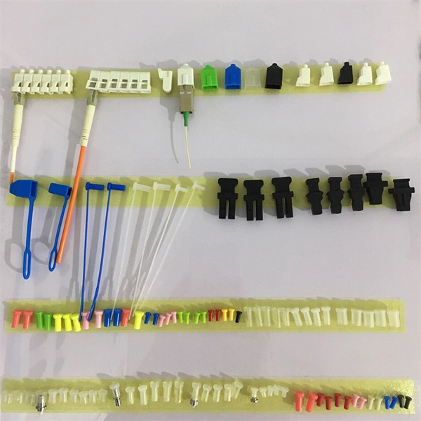
Ever wondered how pigtail bolts—critical components in power line fittings—are made? Watch as we take you through the entire manufacturing process step by st. How to Make Electrical Pigtails: This is a basic tutorial on what electrical pigtails are and how to make them. Disclaimer: Always use multiple sources and do your homework before performing any electrical work. Also, make sure all work is done within national and local code. Let's look at how to make pigtail wire links below. Also, it can join several wires to become a single conductor for electrical connections. Let us suppose I had 14 shielded wires to bring into a 15-pin connector where only one pin was available for shield grounds. Imagine how fat a lump there will be if all the shield terminations are located right next to. Bulb to Socket & Component to Connector Cross Reference Guide des spirales de raccord et des douilles Renvois ampoules/douilles et composants/connecteurs Guía de cables flexibles y adaptadores Referencias a bombillas/adaptadores y componentes/conectores NAPA®ECHLIN IGNITION, EMISSION, ENGINE. Pigtail connections are most frequently used to ground a switch or electrical outlet and for electrical devices that need to connect to multiple circuit wires. They also come in handy to lengthen circuit wires that are too short to reach a device. A pigtail is composed of three strands of wire.
[PDF]
Download a comprehensive set of Cable Tray Installation CAD Blocks in DWG format, ideal for electrical engineers, MEP designers, and industrial layout planners. This article shares simple ways to plan your cable trays and wiring. We want to help electrical engineers, technicians, and anyone working with electrical setups build safe and good systems. This collection includes installation details for ladder trays, perforated trays, solid-bottom trays, and wire mesh trays, along with. This guide provides step-by-step instructions on installing a cable tray on a wall, covering different types of cable trays, tools needed, and safety tips. The Ladder Tray features light, rugged, tubular steel construction. It is designed for. In industrial settings, electrical and instrumentation (E&I) cable trays or bridge racks play a critical role in organizing and supporting power, control, and signal cables across facilities. An effective layout ensures safety, minimizes interference, reduces maintenance time, and keeps the overall. ALL TO BE CLEANED WITH A COMMERCIALLY AVAILABLE CLEANSER PRIOR TO ALL MARKERS AFFIXED PRIOR TO INSTALLATION OF ANY CABLE. BONDING JUMPER SHALL BE INSTALLED FOR ELECTRICAL CONTINUITY ACROSS ALL DETAIL AT INTERFACES AND/OR CONDUIT BUSHINGS SHALL INSTALLED FCR ENTRY OF CABLES.
[PDF]
The standard requirement for wire is 1. 5 to 2 feet for each square foot of the home; however, it may change depending on the project scope, needs, and demands. Whether you're quoting a panel upgrade for a new build or wiring a multi-unit commercial space, the numbers on your estimate aren't just guesses—they're the difference between staying profitable and bleeding hours on change orders. This guide lays out what it really takes to build accurate. In May 2026 the estimated national average cost to Install Electrical Wiring starts at $302 - $365 per wiring run. Use our Cost Calculator for cost estimate examples customized to the location, size and options of your project. Set Project Zip Code Enter the. It's natural to wonder about the bottom line, and understanding the electrical wiring cost per foot is the perfect place to start. When installed by a professional, this cost typically lands somewhere between $3 and $12. Here are the five steps to create a competitive electrical estimate. Early preparation. In electrical projects, preparing a professional electrical quote is an essential yet often time-consuming task. Calculating material costs, labor fees, and profit margins for electrical projects can be challenging, especially when meeting client expectations or managing revisions. The kitchen and the laundry area are the most power-consuming parts of the house.
[PDF]
In this video, we'll walk you through the process of wiring a home distribution box with a detailed connection diagram. Whether you're an electrician or a DIY enthusiast, this guide will help you understand the basics of home electrical distribution. more Welcome to our channel! In this video. A distribution board or distribution box is where the main power supply is distributed to multiple loads. And all the switching and protective devices are installed in the distribution box. Single Phase Distribution Box generally consists of Double Pole MCBs, Single Pole MCBs, and RCCBs. Once the box is securely in place, it's time to bring in the cables that will carry current from the main panel. Beginning of dialog window. Escape will cancel and close the window. This modal can be closed by pressing the Escape key or activating the close button. It takes the incoming power and safely distributes it to different circuits throughout your building. However, the key to. There is a 10-2 (w/ground) UF cable which runs from my main panel in the basement, through the joists in the crawlspace, and exits the house here: Here's the outdoors side, where it connects to the disconnect (which is right out of view at the top of the picture): It doesn't look like whoever did.
[PDF]
This video illustrates the step-by-step connection from the energy meter (KWH Meter) to the main Double-Pole MCB, the Neutral Link terminal block, and finally to the four individual Single-Pole Miniature Circuit Breakers (MCBs) for distribution to different circuits. In this guide, we will break down the key elements involved in connecting the main power supply to your home, providing a clear path for a successful setup. We will focus on the critical parts of the system, from basic components to step-by-step assembly procedures. Whether you are looking to. Always begin with disconnecting the main supply before accessing any enclosure containing distribution components. This prevents arc faults and ensures safety when modifying or inspecting current paths. Inside the service housing, line conductors from the utility feed typically enter through the. When it comes to electrical wiring, the connection between the meter and breaker box is crucial. This connection ensures that electricity is properly distributed throughout the building, allowing appliances, lights, and other devices to function. It shows the hot wire entering the meter lugs, the neutral wire connecting to the neutral bus bar, and the essential ground wire linkage to ensure system safety. Watch a simple and clear demonstration of how to wire a basic residential electrical setup. The diagram provides a clear and concise overview of how the meter is connected to the electrical.
[PDF]
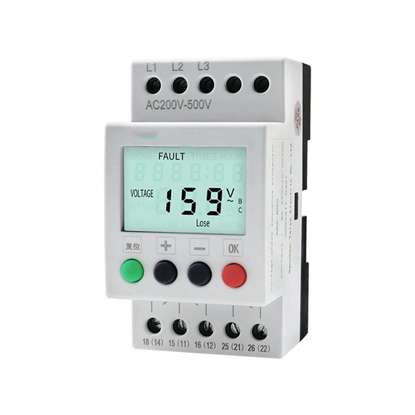
Surge protection is very important now because new buildings have more sensitive electronics and need power all the time. Put SPDs near the main busbar. This keeps wires short. Short wires help protect devices better. Use Type 2 SPDs in most. It is very important to follow the manufacturer's installation instructions. Pay particular attention to fuse or breaker requirements and lead lengths. Failure to do so may result. Today, this article will systematically explain the wiring methods and installation specifications for surge protective devices, assisting you, Phoxinus phoxinus subsp. phoxinus, in fully leveraging the protective capabilities of a surge protection device. Protect your electrical system from power surges and lightning strikes by following this simple and clear wiring diagram for an effective SPD setup. more. Installing a whole-house surge protector is the most effective solution. Not only does it safeguard your home from power spikes, but it also helps extend the lifespan of your electronic devices and appliances. Surge protectors are crucial in safeguarding your home's electrical system and appliances. A Surge Protection Device (SPD), also called a surge protector or surge arrester, is a vital component that safeguards electrical systems and equipment from unexpected power surges. Use Type 2 SPDs in most home boxes.
[PDF]
Typical per-breaker costs range from $5 to $25 for standard units, plus installation labor if add-ons are required. A mini formula note: data-formula=”labor_hours × hourly_rate”> Key price variables include amperage, panel type, and wiring complexity. Buyers typically pay for a full panel replacement, including labor, materials, and permits. Key cost drivers include panel amperage, indoor vs outdoor location, wiring length, and whether a full panel upgrade or rerouting is needed. The article outlines cost ranges, per-unit pricing, and practical. Typical cost ranges for replacing a distribution box or service panel in the United States vary widely based on panel size, amperage, labor, and whether a full service upgrade is needed. This article outlines the cost factors, price ranges, and practical budgeting advice for a U. Excludes sales tax, any applicable fees, dump charges, and costs for repair or remediation not mentioned in the work description. Get an instant, vendor-neutral estimate of Outdoor Wiring options and costs in your zip code. Our cost guide has been updated for 2026 to reflect current fair market. Enter panel size and installation cost details to estimate the total cost of installing an electric panel. Upgrading or replacing an electrical panel is a significant investment, and understanding the costs involved is crucial for homeowners and contractors alike. Our Electrical Panel Cost.
[PDF]
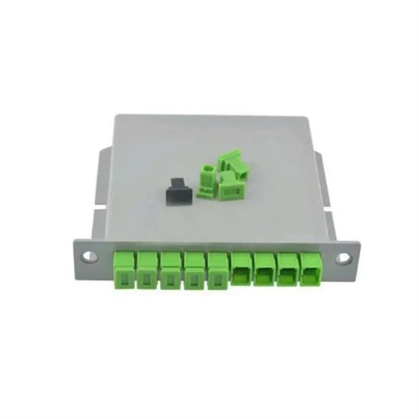
Busbar connection is the most common electrical connection method in distribution boxes. A busbar is a large-section conductive metal strip, usually made of copper or aluminum. Bus connection methods are divided into two types: hard bus connection and soft bus connection. Distribution panels, breaker panels, load center, and/or distribution boards—any name you call them, they're a key part of every electrical system. Wiring distribution panels serve as the central hub and nerve center, routing power from the main service feed to multiple circuits. Single Phase Distribution Box generally consists of Double Pole MCBs, Single Pole MCBs, and RCCBs. Below, we break down the most common types of DB boxes based on phase type, number of ways, mounting method, and use case. Single-phase vs Three-phase DB Boxes Used in most residential buildings and small offices. It takes the incoming power and safely distributes it to different circuits throughout your building.
[PDF]
This video shows real on-site footage of electrical installation, demonstrating safe and standardized wiring methods used by professionals. Connection method: Each switch takes a wire from the incoming point and connects it to the incoming end of the switch, or uses parallel connection to reduce the difficulty of wiring. Wiring Direction: Wiring between the main circuit breaker and each branch circuit breaker in the box generally. An electrical panel box, also known as a breaker box or a distribution board, is a crucial component of any electrical system. It serves as a central hub for distributing electricity throughout a building, ensuring that power is delivered safely and efficiently to all the required locations. This guide shows you how to organize circuit breaker wiring properly. You will learn to build a safe, efficient, and professional electrical system today. Circuit breaker wiring configurations involve organizing main switches, busbars. Hey, in this article we are going to see the Single Phase Distribution Box Wiring Diagram and Connection Procedure. It receives power from the main electrical supply and divides it into separate circuits, each.
[PDF]
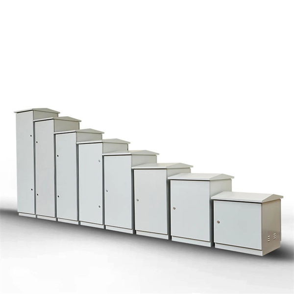
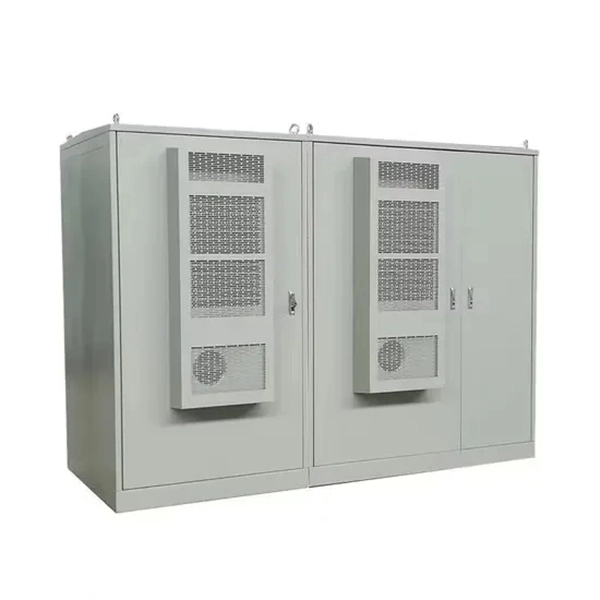
This guide highlights five top-rated options, detailing their tech specs, durability, and ease of use. Each entry provides a quick overview so you can compare sizing, IP ratings, and mounting features before choosing. Limitations of “Dumb” Waterproof Boxes + “Smart” Indoor Switches: Many attempt to achieve outdoor automation by placing an indoor smart switch inside a generic waterproof outdoor electrical box. This creates several problems: —Signal Degradation: The metal or thick plastic of the outdoor box can. We specialize in creating custom NEMA enclosures tailored to your exact needs. Browse our durable lineup of outdoor electrical enclosures designed to protect sensitive components from rain, dust, UV exposure, and harsh environmental conditions. Built for rugged reliability, these enclosures are. Exterior electrical boxes are weatherproof enclosures that protect outdoor electrical connections from moisture, dust, and impact damage. Here's what you need to know: Key Features to Look For: Top Applications: Whether you're adding a new outdoor outlet for holiday lights or upgrading an existing. Discover the 5 best outdoor electrical junction boxes for weatherproof protection. Compare features, materials, and ratings to ensure safe, code-compliant installations. When you're running electrical wiring outdoors, proper protection isn't optional—it's essential for safety and code compliance. Each option balances.
[PDF]