This guide breaks down the five core components of a fiber optic cable — from the specification package to the actual installation considerations. You will also learn how different aspects of the product can affect budget and design. ■ The Five Key Parts of a Fiber . Fiber optic cables are designed to provide high-speed, no-signal-loss, and EMI-free communication in telecommunication, powergrid, datacenter, broadband, and industrial applications. Each optical cable is constructed using a precise combination of optical fibers, strength members, buffer tubes. How does 6W market outlook report help businesses in making decisions? 6W monitors the market across 60+ countries Globally, publishing an annual market outlook report that analyses trends, key drivers, Size, Volume, Revenue, opportunities, and market segments. The material composition determines the fiber's performance, including how far and how fast data can travel. The choice of material is an engineering decision driven by the need to. But are you wondering what materials fiber optic cables are made of? The most common materials are glass and plastic. To transmit information, a datalink converts an analog electronic signal—a telephone conversation or the output of a video camera—into digital pulses of laser light.
[PDF]
A spectrophotometer is a piece of spectroscopy equipment measures the amount of light absorbed by a sample. This measurement can be useful in many research applications: To identify materials by mapping molecular absorption profiles. To work out solute concentrations in solutions. Specifically, a UV-Visible Spectrometer measures the absorption or transmission of light in the ultraviolet (UV) and visible (Vis) regions of the electromagnetic. A spectrometer is a scientific instrument that analyzes light to reveal information about materials. It functions by separating light into its constituent wavelengths, much like a prism splits sunlight into a rainbow. This analytical capability makes spectrometers valuable tools across many fields. Spectrophotometry is an experimental technique that is used to measure the concentration of solutes in a specific solution by calculating the amount of light absorbed by those solutes. It is widely used in laboratories to analyze various substances, from liquids to gases. Here's a step-by-step guide on how to use a spectrophotometer. When you use spectrophotometry, you gain skills that help in many science fields. This guide makes spectroscopy simple by showing you how to use teaching tools and real experiments. The basic principle is that each compound absorbs or transmits light over a certain range of wavelength. This measurement can.
[PDF]
Currently in Revit, there is no material parameter in the cable tray type properties dialog. Use the Object Styles command to set global material setting for Cable Trays Add view filters for the different cable trays to adjust the lines/patterns/transparency values. The most reliable approach is to set the Service Type at the type level, using predefined conduit and tray types in your template. This means the parameter applied. This Revit tutorial walks through setting up cable tray in revit mep, covering essential tools and techniques for your projects. Welcome back to the CAD Teacher VDCI video course content for the BIM 321 course, Introduction to Revit MEP. In this video, we're going to go ahead and start setting up. Electrical BIM only works when the model reflects installation reality, right down to conduit fill, cable-tray loading, and panel schedules that line up with as-built drawings. This indispensable tool seamlessly integrates into your workflow, offering a range of features to enhance efficiency and accuracy. Let's dive into the key aspects of. ConduitMaterial is a plugin for Revit MEP, this tool facilitates the modification of the material in Conduits and Cable Trays, allowing the modification of material of each element as configured in the type properties in the configured parameter 'Material'. Every time you create a Conduit or a.
[PDF]
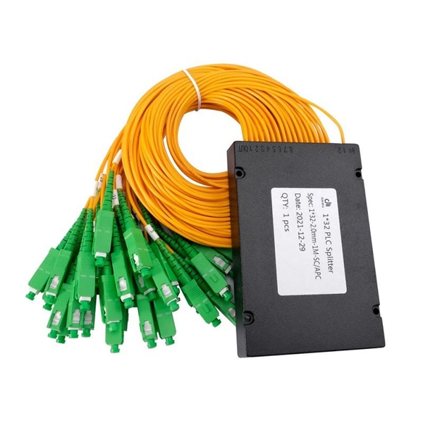
1 × 8 and 1 × 16 traditional/saddle arrayed waveguide grating (AWG) devices with different core layer materials applied in fiber Bragg grating (FBG) system were designed, fabricated and compared. We ap.
[PDF]
We deals in wide range of Supermarket Rack, Display Rack, Supermarket Display Rack, Departmental Store Rack, Retail Store Rack, Hypermarket Rack, Garment Rack, Grocery Rack, Footwear Rack, Departmental Store Rack, Kirana Store Rack, Supermarket Shopping Trolley, Plastic Trolley, Platform. We deals in wide range of Supermarket Rack, Display Rack, Supermarket Display Rack, Departmental Store Rack, Retail Store Rack, Hypermarket Rack, Garment Rack, Grocery Rack, Footwear Rack, Departmental Store Rack, Kirana Store Rack, Supermarket Shopping Trolley, Plastic Trolley, Platform. We are a one-stop shop for top-notch Electrical Cable Tray in Botswana. Our cable trays are manufactured from robust materials and rigorously tested to ensure they can withstand even the most demanding environments. We, one of the top Electrical Cable Tray Manufacturers in Botswana, offer a wide. Looking for a trusted source to buy Cable Tray In Botswana? Brilltech Engineers Pvt. Ltd is the one you can reach. We have a highly experienced team, well-loaded manufacturing unit and a lot more to match up the ever-evolving needs of our customers. Moreover, our focus on maintaining high quality. Cable trays support insulated electrical cables in industrial and commercial settings. There are several types of cable trays, including ladder, perforated, solid bottom, basket, and channel trays. We believe in building fruitful business partnerships. What is Cable Tray Systems? 1. Being one of the.
[PDF]
Then, according to the short-circuit current parameters, the relay protection of transmission lines, transformers, busbars, etc. is set, and the configured protections include current quick-break protection, gas protection, and longitudinal differential protection. Generator protection covers: phase-to-phase short circuits in stator windings, stator ground faults, inter-turn short circuits in stator windings, external short circuits, symmetrical overload, stator overvoltage, single- and double-point grounding in the excitation circuit, and loss of excitation. Explore principles and configurations of protective relaying in high voltage systems. Ensure fast, selective fault clearance per IEC/IEEE standards. Abstract: In this paper, the main electric wiring mode of 110kV. Relay protection is essential to ensure the stability, reliability, and safety of electrical power systems. In HV (High Voltage) and MV (Medium Voltage) substations, relay protection safeguards critical assets such as transformers, circuit breakers, and lines. Effective relay protection depends on. A protection relay is an intelligent device used to monitor electrical parameters such as current, voltage, frequency, and phase angle. Finally, a comprehensive.
[PDF]
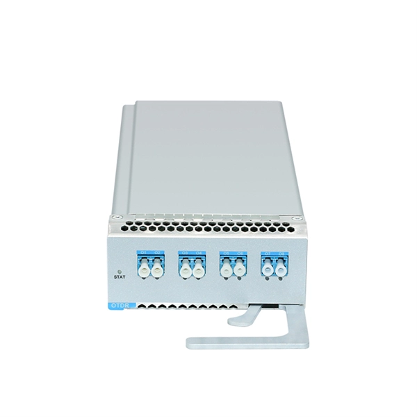
Two fiber ports (TX and RX) side-by-side. Simplex LC: single fiber port. Used for BiDi (Bidirectional) modules where data is sent and received on the same strand using different wavelengths. SFP (Small Form-factor Pluggable) is a compact, hot-pluggable network interface module used to connect network devices (switches, routers, firewalls) to fiber optic or copper cables. Think of it as the “translator” for your network equipment, converting electrical signals into optical signals. The optical module serves as a crucial component in optical fiber communication systems, operating at the physical layer, which is the lowest layer in the OSI model. Its primary function is to achieve optoelectronic conversion by converting electrical signals into optical signals and vice versa. An. An optical module is mainly composed of optoelectronic devices (including the optical transmitter and optical receiver), functional circuitry, and optical interfaces. Optical modules typically have an electrical interface on the side that connects to the inside of the system and an optical interface on the side that connects to the outside. Whether you're selecting an optical transceiver module for short-range multimode applications or long-haul coherent transmission, understanding these parameters ensures reliability and performance.
[PDF]
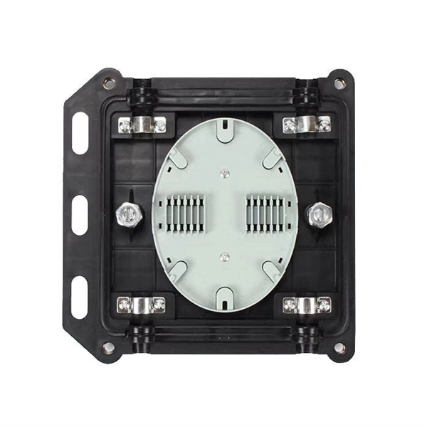
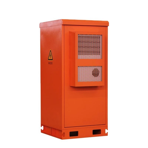
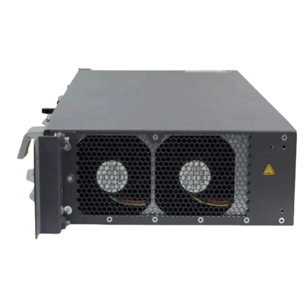
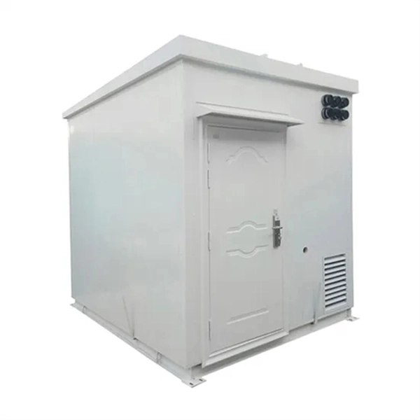
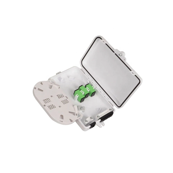
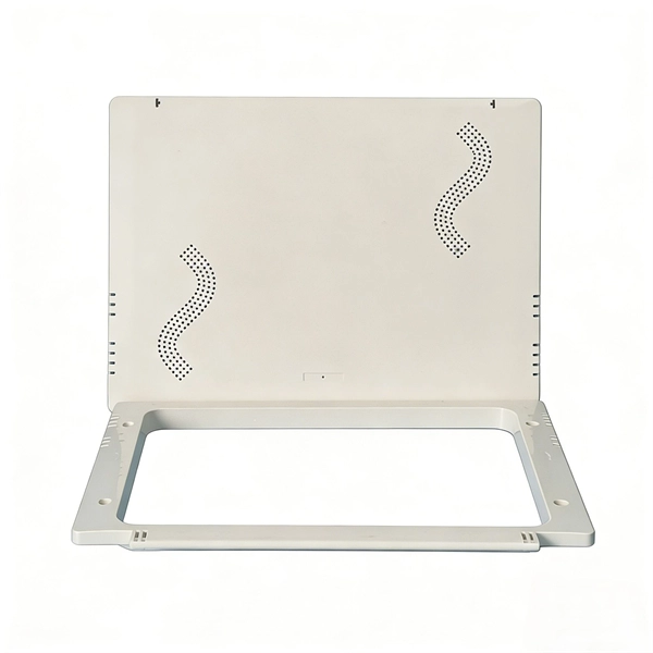
The most common types include distribution cabinets, control panel enclosures, network cabinets, switchgear cabinets, and junction boxes. It ensures that electricity is delivered safely and efficiently to different sections of a building or facility. In electrical engineering, a power distribution cabinet refers. Electrical control panels and distribution boxes are the backbone of modern electrical systems. From powering homes and industrial facilities to supporting medium-voltage infrastructure, these enclosures ensure safe, efficient, and reliable power distribution. Whether it's a small electrical. Electrical cabinets are specialized enclosures designed to house electrical components, controls, and distribution systems in industrial and commercial settings. Distribution boxes can be found in a range of sizes and shapes, designed to match the complexity and power needs of the building. Common installation spots include electric rooms, basements, and corridors, making them accessible for maintenance and troubleshooting. The hub distributes electrical power from a single input source to various circuits throughout a. Distribution boxes can be classified in different ways depending on the installation environment, enclosure material, and mounting method. In practical projects, these categories are often used together rather than treated as a single flat list. Indoor distribution boxes are used in protected.
[PDF]
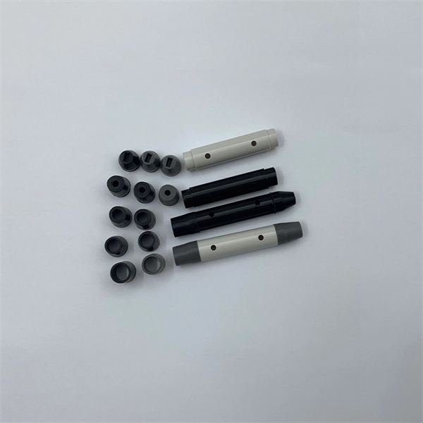
In this article, we will explore the different types of fiber optic pigtails, focusing on the distinctions between single-mode and multi-mode pigtails, and the unique applications for which each type is best suited. Executive Summary: A fiber optic pigtail is one of the most commonly specified yet least understood components in structured cabling. Get the wrong connector type, the wrong polish, or skip proper fusion splicing technique—and you're looking at elevated signal loss, increased back reflection, and a. In this guide, we'll break down what fiber optic pigtails are, how they work, their types, and how to choose the right one for your application. What Is a Fiber Optic Pigtail? A fiber optic pigtail is a short optical fiber cable that has a connector on one end and an exposed (unterminated) fiber on. A Fiber Optic Pigtail Complete Guide: As per types, connectors, and applications. In such contemporary fiber optic communication systems, low-loss, and connectivities, which have reliability, are crucial for not only maintaining high-speed but also high-quality data transmission. The most urgent. A fiber optic pigtail is a short length of optical fiber —typically 0. 5m to 2m—that has a factory-terminated connector on one end and bare fiber on the other end. The connector end is polished and tested under factory conditions, ensuring low insertion loss and high return loss.
[PDF]
Modern fiber-optic communication systems generally include optical transmitters that convert electrical signals into optical signals, optical fiber cables to carry the signal, optical amplifiers, and optical receivers to convert the signal back into an electrical signal. Their performance directly impacts the transmission quality of optical signals and the stability of the link. Whether in data centers. There are so many different ways to approach optical communication, and every device has its own list of pros and cons. In modern, dense networks, small form factors are a constant necessity. Without such interfaces, you simply can't pack enough networking components into the limited space that is. LC (Lucent Connector) interface: The LC interface is a small optical fiber connector that is commonly used for high-density optical fiber connections, such as equipment connections in data centers and enterprise networks. The common types mainly include the following: 3. 1 SC optical fiber connector: It is a large square. Fiber Optics or Optical Fiber is a technology that transmits data as a light pulse along a glass or plastic fiber. An Optical Fiber is a cylindrical fiber of glass that is hair-thin in size or any transparent dielectric medium. The fiber which is used for optical communication is waveguides made of.
[PDF]
Optical fiber consists of a and a layer, selected for due to the difference in the between the two. In practical fibers, the cladding is usually coated with a layer of or. This coating protects the fiber from damage but does not contribute to its properties. Individual coated fibers (or fibers formed into ribbons or bundles) then ha.
[PDF]