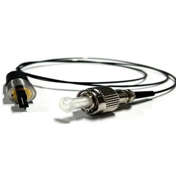
As illustrated in typical SFP internal structure diagrams, the module's core components include an optical transmitter assembly (TOSA), laser driver, optical receiver assembly (ROSA)—some high-sensitivity modules (like L16. 2) use APD receivers, which require an additional booster. As a key element in optical communication systems, optical transceivers serve as media between network devices to transmit and receive data. There has been lots of articles and guides on transceiver modules in the perspective of the package type while only a few of them cover the internal elements. Optical modules are devices used to connect network devices, transmit and receive data between network devices, and can be used to convert optical and electrical signals. The optical module is a very important component in an optical communication system. When you remove the metal housing of the optical transceiver, you will find that the internal components are connected to each other. The following section will focus on. In the era of 5G, AI, and high-speed data centers, optical modules serve as the core bridge for converting electrical signals to optical signals (and vice versa), enabling fast, reliable data transmission across networks. Among various optical module form factors, SFP (Small Form-Factor Pluggable). The optical transceiver module is mainly composed of three parts: housing, optical device and integrated circuit board. The following section will focus on.
[PDF]
Huawei QSFP-40G-LR4 40GBASE-LR4 QSFP+ optical module, 40G single-mode up to 10km via LC duplex for Huawei 40G switches. Request live stock & price. Targeting network engineers and IT procurement specialists, this module ensures high-speed, long-distance data transmission with reliable performance. The 40G QSFP+ LR4 is a transceiver module designed for 10km optical communication applications. The design is compliant with 40GBASE-LR4 of the IEEEP802. The module converts 4 inputs channels (ch) of 10Gb/s electrical data to 4 optical signals and multiplexes them into a single channel. Sorry, it doesn't seem to be a valid email address. The Huawei 40G Base-LR4 Optical Transceiver, QSFP+, 40G, Single-mode Module (1,310 nm, 10 km, LC) is guaranteed 100% Compatible and Functional in its intended equipments.
[PDF]
These modules are engineered with high-grade components designed to withstand the vibrations of washboard forest service roads and the temperature swings of high-altitude passes. 00 Original price was: $46. Activates High current relay when High Beams are turned on, used to add large light bars and driving lights without having to install additional switches in the dash. Plugs directly into Polaris Pulse System for switch lighting and keyed on ignition. The CanM8 Cannect Duo (Speed Pulse & High Beam) Interface is a 2-output CAN Bus interface which provides a quick solution for detecting high beam activity on vehicles which feature CAN Bus wiring. The Cannect Duo Interface also features a square pulsed speed signal output from the vehicle at a. Electronic technology has advanced so that an electronic control unit (ECU) is required to control the functions of full LED automotive headlights. An ECU consists of mainly LED drivers for headlight functions such as high beams, low beams, daytime running lights, position lights, turn indicators. This module resolves the issues with the headlight turning off, or flashing after the ignition is turned on. This issue is mainly affecting Chrysler, Jeep, Dodge vehicles, but some other modern cars will have this same issue. They offer a true plug-and-play experience, effectively eliminating the common flickering issues associated with.
[PDF]
The Optical Module Chip Base is a critical packaging platform designed to support core components such as laser chips, detector chips, and driver chips in high-speed optical communication modules. The primary optical communication devices used are optical modules and optical chips, which are essential for high-speed data transfer and network interconnection. It serves as a bridge between the chip and external optical fibers or circuit systems, ensuring. In the backbone of the global digital infrastructure, optical modules are the unsung heroes, converting electrical signals into pulses of light and back again, enabling the high-speed data transmission that powers the internet, cloud computing, and telecommunications. At the heart of every advanced. An optical module is a device that converts electrical signals into optical signals and vice versa. Among various optical module form factors, SFP (Small Form-Factor Pluggable).
[PDF]
This report studies the global Optical Module PCB Board production, demand, key manufacturers, and key regions. Optical Module PCB Board by Application (Optical Receiving Module, Optical Transmitting Module, Optical Transceiver Module, Optical Forwarding Module), by Types (Single-layer PCB, Double-layer PCB, Multi-layer PCB), by North America (United States, Canada, Mexico), by South America (Brazil. Dongshan Precision plans to acquire Taiwan's Source Photonics for up to $850 million to expand its optical communications business. The deal, which aims to integrate Source Photonics' vertically integrated operations and high-speed optical module capabilities, is pending approval from Taiwan's. The Optical Module PCB Board market is experiencing significant growth, driven by the increasing demand for high-speed data transmission in various industries, including telecommunications, data centers, and consumer electronics. These printed circuit boards (PCBs) play a vital role in connecting. The global Optical Module PCB Board market size was US$ million in 2024 and is forecast to a readjusted size of US$ million by 2031 with a CAGR of %during the forecast period 2025-2031. The Optical Module PCB Board Market is expected to grow from 2,490 USD Million in 2025 to 5. 8 USD Billion by 2035. This report is a.
[PDF]
Quick Answer: To check CPU utilization on a Cisco switch, use the command “show processes cpu” in the CLI. This displays current CPU load, CPU usage history, and process-specific details, aiding in network performance troubleshooting. The CPU becomes too busy when either an IOS process consumes too much CPU time or the CPU receives too many packets from the switching hardware. When either of these two CPU consumers requires the CPU resource to the detriment of the other, then the CPU is too busy. For instance the CPU is. High CPU utilization on Cisco switches can lead to degraded network performance, packet loss, and even switch failures. Identifying and troubleshooting the root cause of high CPU usage is essential for maintaining a healthy network. In this article. I noticed that after having VLANs, ClearPass, spanning tree, and all other settings configured, that CPU util was just sitting at or above 85% on all these switches. I updated firmware to the latest version on all of them, but that didn't help. Problem analysis process 1. According to the switch logs, after searching for related processes, we can find that the. my switch core has high CPU usage every 3 minutes, switch logs attached. Do the outages/CPU spikes occur at the same time as the log entries appear such as : 00828 lldp:. Thank you, Fix the problem indicated.
[PDF]
This simple step resolves many issues with sfp optical transceivers in access switches and core routers. Test with a known-good module or patch cable. If the issue persists, suspect either the switch port or external fiber path. Read TX/RX power, bias current, voltage, and. Optical transceivers play a crucial role in modern data communication networks, enabling the transmission and reception of optical signals across fiber-optic cables. However, like any other electronic component, optical transceivers can encounter issues that may affect network performance. This guide. This guide provides a deep technical overview of how to troubleshoot sfp optical transceivers and other optical transceivers module types effectively in 2025. These compact devices convert electrical signals to optical signals and vice versa, enabling data transmission over fiber optic cables. We'll discuss how to identify the issue, possible causes of optical transceiver issues, troubleshooting steps, and. Have you ever experienced an unexpected network outage due to the failure of an SFP/SFP+ optical transceiver? Network outages can bring your ability to communicate and work to a halt, and your IT team will likely be frantically looking for a solution. It is important to understand how to.
[PDF]
Optical trap or "tweezers" is a device used to apply piconewton sized forces and make precise measurements on a scale of roughly one micron. It can be created by applying a precisely focused laser onto a dielectric material. Thorlabs' OTKB (/M) Modular Optical Tweezers provide users with a tool for trapping and manipulating microscopic-sized objects. These laser-based tweezers, or traps, have been employed in numerous biological experiments. Biological applications for optical tweezers include trapping viruses and. Our advanced optical trap generator based on ultra-fast AOD technology. Versatile and flexible optical trap manipulation designed for biological samples. Learn to calibrate the 20. Use calibration information to observe the rotation of E. coli bacteria, and determine the forces required to stop this rotation. Based on their design, Thorlabs has collaborated with the aforementioned authors to design an OTKB optical trapping kit that includes all necessary components and provides the same capabilities. Enclosed into a high-quality aluminum box and assembled onto the. Torr Scientific offers a range of magneto-optical traps (MOT) (also known as atom trap chambers) used as part of ultra-cold vacuum systems, to capture atoms for testing purposes. This is a chamber module, formed of low-magnetic permeability materials for use at ultra-low temperatures nearing.
[PDF]
GPON is an alternative to Ethernet switching in campus networking. GPON replaces the traditional three-tier Ethernet design with a two-tier optic network which eliminates access and distribution Etherne.
[PDF]
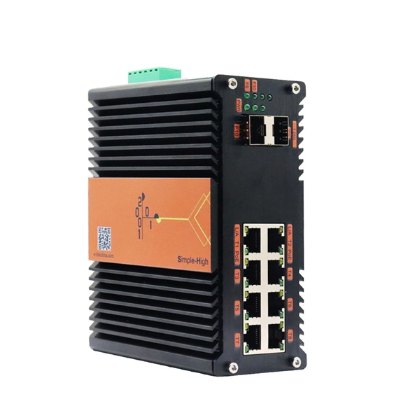
The base station can be divided into two modules: the RRU for transmitting signals and the BBU for processing signals. The BBU is small and exquisite, with low power consumption, while the RRU is large and has high power consumption. Which optical modules are commonly used in 4G base stations? In this blog, ETU-LINK will talk about 4G base stations and common types of optical modules. The BBU is small and. In a mobile communication base station, the antenna is at the top of the signal tower, and under the tower is the machine room, in which the base station is placed. Generally, the. RRU and BBU are crucial components in base station construction, enabling a distributed architecture that improves efficiency and reliability. Here's a breakdown of each: The central processing unit in a base station. Handles baseband signal processing, transmission scheduling, and network interfacing. BBU is used for signal processing, RRU is used for signal transmission and reception, and the feeder is used to connect the antenna and the base. The base station is logically divided into two parts: BBU and RRU. RRU is responsible for signal transmission and reception, and BBU is responsible for signal processing. The feeder is used to connect the antenna and the base station, and the supporting equipment is mainly the power supply and air.
[PDF]
A common test setup to evaluate Stressed Receiver Sensitivity involves measuring the Optical Modulation Amplitude (OMA) using a square wave, per the standard guidelines. Receiver sensitivity stands as a critical parameter impacting an optical transceiver's functionality. It denotes a module's capability to function in challenging environments and aids network operators in determining the system's maximum reach or link margin. These metrics provide insights into how well your transceivers perform under different conditions, ensuring seamless data transmission. Optical. Whether you're a network engineer validating new inventory or an integrator preparing for deployment, knowing how to test optical transceiver modules can save time, reduce failures, and ensure SLA compliance. Unchecked optical modules can cause: Testing ensures compliance with IEEE 802. 3 and MSA. In optical communication systems, sensitivity is a measure of how weak an input signal can get before the bit-error ratio (BER) exceeds some specified number. The standards body governing the application sets this specified BER. For example, SONET specifies that the BER must be 10 -10 or better. Why Fiber Optic Transceiver Testing is Important? Identify faults and failures: Transceiver testing helps in identifying any faults.
[PDF]
In the field of optical communication, the packaging of optical devices plays a crucial role in the performance and application of optical modules. Common optical device packaging methods include COB (chip-on-board packaging), BOX and coaxial packaging. Today, we will discuss the differences. This article analyzes the requirements of optical transceivers and discusses packaging methods and optical chip types to help readers better understand their design and manufacturing process. They are used in telecom and data communication applications and can be packaged in different ways, including TO, Box, and COB packaging. Regardless of the type of optical module, the. COB packaging means chip-on-board packaging, and the laser chip is adhered to the PCB substrate, which can achieve miniaturization, light weight, high reliability and low cost. The traditional single-channel 10Gb / s or 25Gb / s rate optical module uses SFP package to solder the electrical chip and. The optical transceiver module has three major components, which are opto-electronic devices (TOSA/ROSA), a circuit board with electronic components (PCBA) and optical interfaces (housings) such as LC, SC and MPO. Figure1: Components of an Optical Transceiver The optical transmitting part is.
[PDF]
Optical modules typically have an electrical interface on the side that connects to the inside of the system and an optical interface on the side that connects to the outside world through a fiber optic cable. An optical module is a typically hot-pluggable optical transceiver used in high-bandwidth data communications applications. Composition of Optical Modules The optical module, known as Optical Transceiver in. The optical module serves as a crucial component in optical fiber communication systems, operating at the physical layer, which is the lowest layer in the OSI model. Its primary function is to achieve optoelectronic conversion by converting electrical signals into optical signals and vice versa. Operating at the physical layer of the OSI model, optical modules are core devices in optical.
[PDF]
OMD-1800 is a bidirectional passive CWDM multiplexer/demultiplexer designed to transmit multiple optical channels over a single fiber. Supporting up to 18 wavelengths, it enables efficient point-to-point fiber utilization while maintaining low insertion loss and high channel. The Model 0201 OMD is a high capacity optical media shredder listed on the NSA/CSS EPL for CD destruction. It is also NSA/CSS EPL listed for DVD destruction through 2024 and meets DIN 66399 Level O-5 standards. The unit produces a residual particle size of 2. This optical. Everything you need to build an optical network from end-to-end. Thin-film filter and PLC based AWG for multiplexing, a full suite of components for optical amplification use, optomechanical or MEMS-based switches for protection or surveillance application, Tap PD for power monitoring and VOA for. The Model 0202 OMD Optical Media Destroyer is a system designed specifically for the destruction of Optical Media (CDs, DVDs). The system has been evaluated by the NSA, meets the NSA/CSS 04-02 Standards and is listed on the NSA Evaluated Products List. By audiobomber January 24 in Buy & Sell Audio and Computer Components This is the latest design and the currently-offered audiophile-grade fiber media converter (FMC), designed for Sonore by John Swenson to isolate network noise. Some erroneously refer to this model as a v3, but there is no v3.
[PDF]
Your eyes contain two types of light-sensing cells: rods and cones. Rods detect low-light vision and motion, while cones handle color vision and detail in bright light. Damage to either can lead to vision problems like night blindness or color blindness. Protecting your eyes with proper nutrition. Personnel Safety. Optical Touch Buttons. Self-contained Sensors. Each technology has unique strengths and weaknesses, so the requirements of the application itself will determine what technology should be used. This article is focused on photoelectric sensors and defines what they are, their adv ors are readily present. Quality Control: They can detect defects, ensure proper product placement, and verify the presence of components. Safety: They can be used to create safety barriers, preventing machinery from operating when a person or object is in a hazardous zone. In this section, we explore the geometric optics of the eye. Early thinkers had a wide array of theories regarding vision. Euclid and Ptolemy believed that the eyes emitted rays of light;. Understanding the eye involves examining how its individual parts contribute to the overall function. Vision begins as light enters the eye through the cornea, a transparent, dome-shaped outer.
[PDF]