The standard industry practice is to set overload relays at 125% of the motor's nameplate Full Load Ampere (FLA) rating. Plug Setting Multiplier (PSM) indicates how many times the determined relay secondary current (typically the CT secondary) exceeds the relay pickup (plug) current. It is the key quantity utilized in IDMT (inverse definite minimum time) curves to calculate the basic operating time. PSM (Plug Setting. An overload relay is a crucial device for motor control, designed to prevent motors from overheating or suffering winding damage due to excessive current. Motor overload relays protect against sustained overcurrent conditions that cause dangerous overheating, insulation breakdown, and premature. Overload relays protect motors and equipment from thermal damage caused by prolonged overcurrent conditions. IEC 60255 defines standards, formulas, and performance requirements, enabling accurate calculations and real-world applications. How is the overload relay current calculated? Why include. Setting motor overload relays correctly is critical for protecting AC induction motors from sustained overcurrent conditions while avoiding nuisance trips during normal starting transients. This occurred when the relay F was set at 1. The complaint was that the relay tripped instantly on overload when the thermal damage curve show plotted for a specific current that was less t an.
[PDF]
LV overhead lines are protected against overcurrents using fuses or circuit breakers. Protection of MV overhead lines is usually achieved by overcurrent relays (50; 50N; 51; 51N; 67; 67N) connected to.
[PDF]
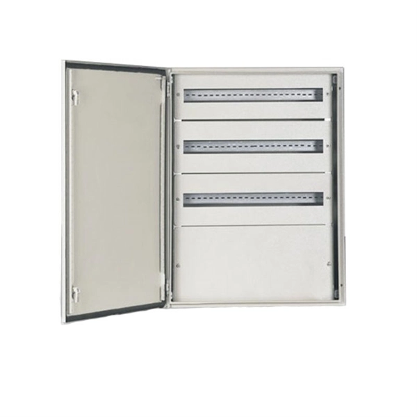
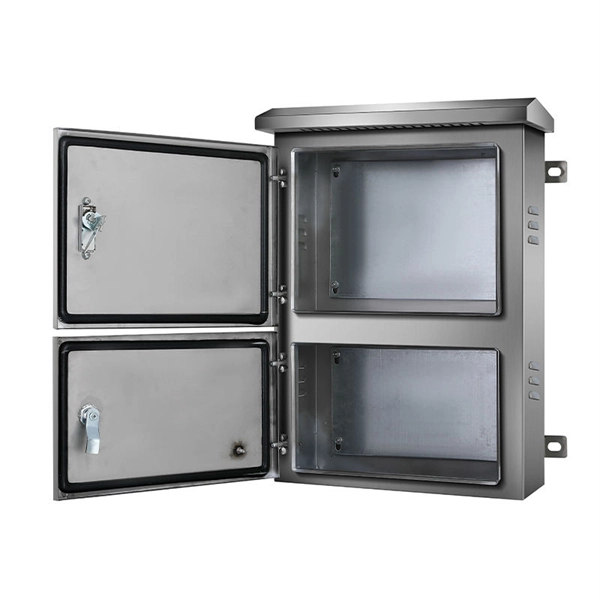
Browse enclosures designed for easy installation and cooling of enclosed equipment. Crafted from durable pre-galvanized steel, these boxes are designed to house wiring devices such as switches or outlets. With RACO's Switch Electrical Boxes, convenience is key. The device mounting holes are pre-tapped to. Power and Low Voltage Box For New Construction, Nail On. Low Voltage Side Provides Combination 1/2" and 3/4" Knockout. This intelligent fire emergency lighting system utilizes a centralized power controller distribution box, complying with the GB-17945-2010 standard, and provides over 90 minutes of emergency runtime. The system comprises an emergency lighting controller, a centralized power supply (EPS), and. Electrical Junction Box, Ventilated Design, Cable Grommets, Indoor/Outdoor Use with Mounting Panel & Hinged Cover. (Grey Cover, 13"x13"x5. 1") Need help? Streamline your home wiring and media setup with low voltage panel boxes. “Value After Rebate*” is the price or sale price minus the future rebate discounts. Valid on merchandise; excludes purchase of gift cards, rentals. For new construction and retrofit projects! Arlington's convenient combo box has power and low voltage openings in the same box, saving you time and money. LVD2, designed for new construction, comes with nails in place, ready for attachment to wood studs. Holes in the front flanges allow for screw.
[PDF]
Single Line Drawing of the LV Distribution Network with feeder pillars and distribution boxes, showing cable length, size, voltage drop, and percentage voltage drop. All orders over MVR 300 qualify for free delivery, while orders under MVR 300 are subject to a MVR 50 delivery fee. In addition, we do delivery of goods up to Jetty/boat. In cases where the goods are requested to be delivered to a vessel, details. Let us help you with your questions and queries. Send a message to Viber: 7317894 Promotions, new products and sales. Directly to your inbox. If Datasheet includes multiple models, the model number should be highlighted Datasheet of Transmission equipment. Busbar configuration, dimensions, materials and rating. Single Line. © 2024 E-Talk Maldives. Nuomak is proud to announce a new cooperation with a client in the Maldives, for whom we have manufactured PS cabinets, MCCBs, and transparent waterproof electrical distribution boxes. These products are specially designed to meet the challenges of high humidity, salt spray, and harsh coastal. Can't find the product you need? Please give us feedback Dongfeng-covering various types of distribution boxes_rich and diverse product system, covering various types of distribution boxes and cabinet products.
[PDF]
An analog accessory for use in a system for testing protection relays is provided, comprising inputs connectable to the current outputs of a test-set for protection relays and voltage outputs connectable to a protection relay to be tested. The register contains national patents and information related to European Patents validated in Malta. It currently provides European patent numbers, filing dates, titles, abstracts, classifications, applicants, bibliographic data, status, priorities, expirations, annuity/renewal fees. The utility model discloses a power plant relay protection tester, belonging to the technical field of relay protection testers, which comprises a relay protection tester body and a shell for placing the relay protection tester body, wherein a partition plate is arranged in the shell, a driving. Application to amend a patent application or registration. Convert a European patent application to a National patent. Request an extension of a time limit for the submission of patent documents. By providing an electric circuit adapted to convert current. Background Relays and metering are an important part of power generation, power transmission, and power con- sumption in electric power systems and the power grid. Relays provide monitoring and protection of equipment and personnel.
[PDF]
In the ring distribution network, differential relays, which rely on communication between the protection relays, are used for the underground cable protection. To guarantee cable protection when communication is failed, an auxiliary protection by using directional overcurrent. This solution is based on Recommendation ITU-T G. 1344, which defines the protection switching protocol and mechanisms for Ethernet ring network topologies which will be described in detail in this document. This guide is intended for Alcatel-Lucent Enterprise's Business Partner sales and. The G. This feature uses the G. 8032 Ethernet Ring Protection (ERP) protocol version 1, defined in ITU-T G. 8032, to provide protection for Ethernet traffic in a ring topology with. Fiber rings provide resiliency to protect network services, but Spanning Tree for Ethernet rings does not provide fast failover when a link in the ring fails. In. Distance relays are applied as short-circuit protection in almost all transmission systems where overcurrent relays cannot be used for reasons of selectivity, fault detection requirements or where there is a need for improved fault clearing times. They are mainly applied in ring networks with.
[PDF]
Below is a list of best universities in the United States ranked based on their research performance in Firefighting and Fire Science. Explore the best colleges with fire protection and prevention degrees. Read more on how this ranking was calculated. A graph of 221K citations received by 5. 06K academic papers made by 48 universities in the United States was used to calculate publications' ratings, which then. Looking for colleges with a Fire Protection Major? See a list of colleges with Fire Protection here to evaluate admissions data, tuition, rankings and more. Access exclusive rankings for colleges and universities around the country. Our AI model can make mistakes. Double check important details. What's on this page: * Degree-Level Rankings Your choice of fire. The educational requirements for a protective relay technician are a combination of high school diploma, certificate, and associate degree. According to the data, a certificate in a relevant field is held by 50. 33% of protective relay technicians, while 39. 1% have an associate degree. Fire protection and safety technology majors are the most popular in California (60 schools), North Carolina (23 schools), Florida (19 schools), and Texas (13 schools). The best protection.
[PDF]
This paper discusses some practical aspects of implementing single-pole tripping schemes in transmission-line protection. Implementation and techniques will vary in the design of protective relaying systems that i.
[PDF]
Earth fault protection based on measured or calculated residual current values: If a breaker fails to be triggered by a tripping order, as detected by the non-extinction of the fault current, this backup protection sends a tripping order to the upstream or adjacent breakers. In electric power systems and industrial automation, ANSI Device Numbers can be used to identify equipment and devices in a system such as relays, circuit breakers, or instruments. The device numbers are enumerated in ANSI / IEEE Standard C37. 2 Standard for Electrical Power System Device Function. In North America protective relays are generally referred to by standard device numbers. ANSI IEEE Standard Device Numbers are below: (the more commonly used ones are in bold) 86T is a Lockout Relay for a. The ANSI standard device numbers ( As per ANSI/IEEE standard C37. 2) are used in the design of an electrical power system. The list of ANSI device numbers with their acronyms is as given below. Save my name, email. The protection and control devices in electrical equipment can be referred to by numbers, with appropriate suffix letters when necessary, according to the functions they perform. Even in those parts of the world where IEC standards are predominate, the use of ANSI numbering. There are two methods for indicating protection relay functions in common use. The functions are supplemented by letters where amplification of the function is required. The other is given in IEC 60617 and uses.
[PDF]
The total interruption time for a modern high-voltage SF6 circuit breaker is typically between 40 to 60 milliseconds on a 50Hz grid, or 2 to 3 cycles. This is the total time from the trip signal to the final arc extinction, a critical parameter for grid safety. While knowing the total time is a. When a SF6 circuit breaker (CB) hits its critical low pressure, its fault interrupting capability can be compromised. Most TOs protect against this by either auto-opening the CB prior to reaching the critical low-pressure level or by blocking the CB from tripping (when it reaches the critical. The protected zone is defined and limited by different things depending on the protection function. Definite time delay means that the protection operate time dose not change or depend on the fault type or the fault current magnitude. Instead of oil, air, or a vacuum, a sulfur hexafluoride circuit breaker uses sulfur hexafluoride (SF 6) gas to cool and quench the. Page 1 Content Instruction Manual circuit- breaker GL317 With spring operating mechanisms FK3- 4 Administrator First issue Compiled by Approved by 19- 11- 2012 J. Texier Imagination at work Grid Solutions 04- 2017 D1736EN/03 GE Information 1/10. Page 2 Content Instruction Manual This. A comparison of the time it takes protective devices to operate when certain levels of normal or abnormal current pass through them. LV circuit breaker ratings.
[PDF]
Relays may be fitted with a "target" or "flag" unit, which is released when the relay operates, to display a distinctive colored signal when the relay has tripped.OverviewIn, a protective relay is a device designed to trip a when a is detected. The first protective relays were electromagnetic devices, relying on coils operating on moving par. Electromechanical protective relays operate by either, or. Unlike switching type electromechanical with fixed and usually ill-defined operating voltage thresholds. Electromechanical relays can be classified into several different types as follows: "Armature"-type relays have a pivoted lever supported on a hinge or knife-edge pivot, which carries a moving contact. These relays may.
[PDF]
This forces distribution transformers to be located within several hundred feet of each customer, but eliminates the reliability concerns associated with T-splices that are required to connect underground servic.
[PDF]

The SEL-221F Relay uses positive-sequence memory voltage polarized mho distance elements for phase and ground distance protection. These elements expand in proportion to the source impedance to provide more resistive fault coverage than self-polarized mho elements. VAMP 221 arc protection system components. Central unit VAMP 221. I/O units VAM 12L / VAM 12 LD, VAM 10L / VAM 10LD, VAM 3L / VAM 3LX and VAM 4C / VAM 4CRL / VAM 4CD 10 1. Arc sensors VA 1 DA, VA 1 EH, ARC SLx. Schneider Electric VAMP range is an arc flash detection and protection pioneer offering fast and reliable devices to improve safety. VAMP 221 significantly reduces the risk of potential personal damage, and material and production losses caused by arc fault. VAMP 221 complies with the latest standards concerning the. Serial communications ports allow local or remote interaction with the relay. 5” high chassis sizes. The report will identify methodology behind these practices, present issues raised by the integration of microprocessor relays and the internal logic and external communication configurations, ying. In the design of electrical power systems, the ANSI Standard Device Numbers denote what features a protective device supports (such as a relay or circuit breaker).
[PDF]
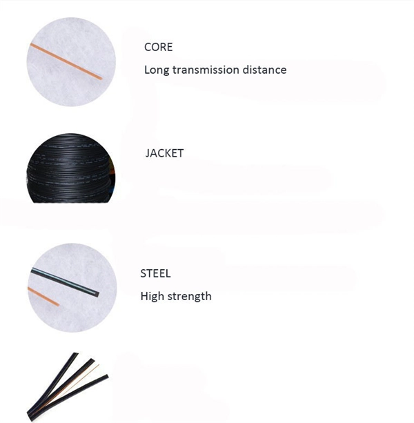
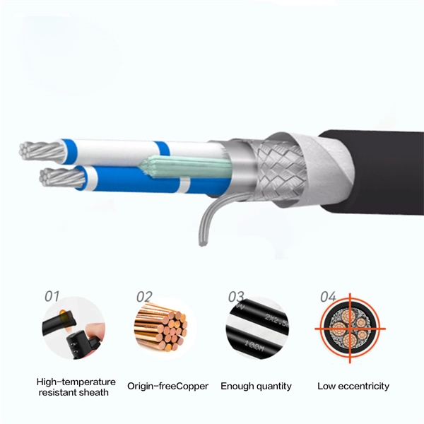
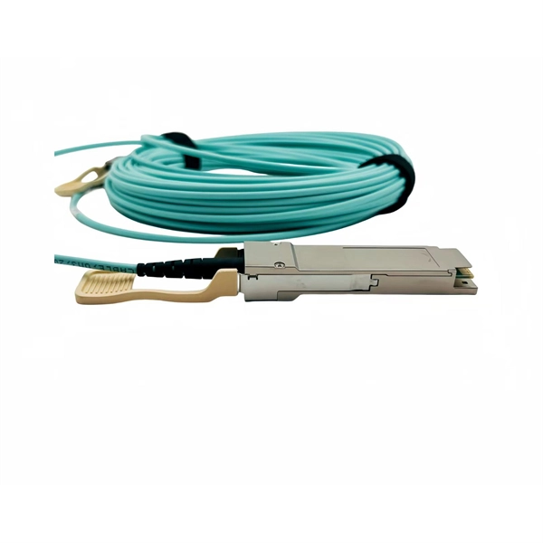
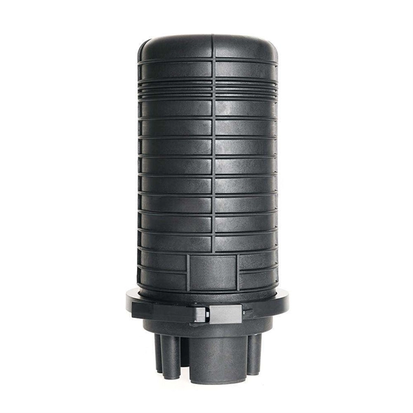
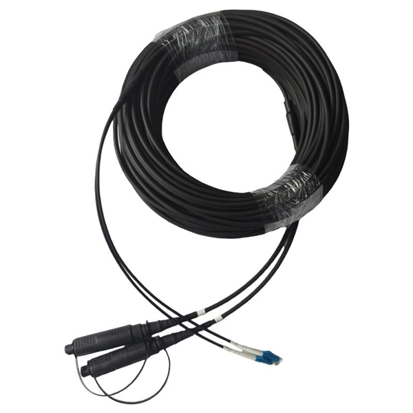
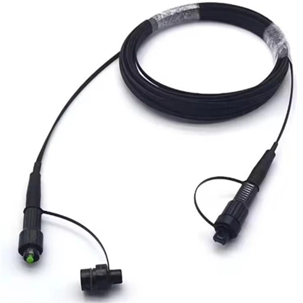
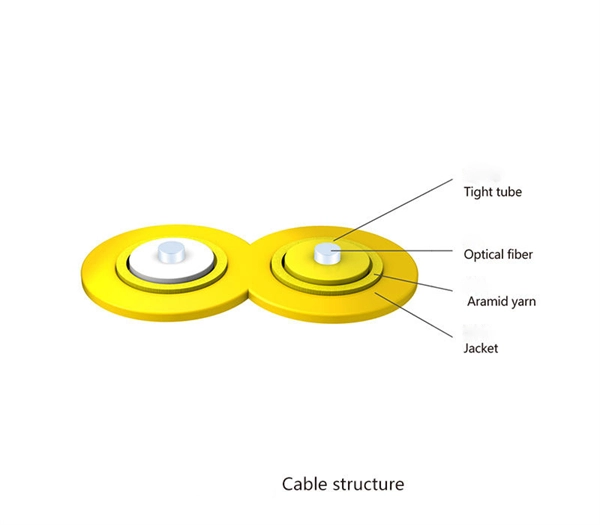
A2: According to EIA/TIA-598, the fiber optic cable color code defines the jacket color codes for different fiber types (SMF or MMF). Fiber optic color codes provide the essential identification framework that enables fiber technicians and network professionals to manage complex optical network installations efficiently. This standardized fiber optic color coding system helps prevent costly connection errors while dramatically. Understanding fiber‑optic color codes is essential for any technician tasked with installing, maintaining, or troubleshooting modern fiber networks. By adopting the TIA/EIA‑598C standard, you gain a universal “language” of colors that speeds identification, reduces miswiring, and enhances safety. The TIA-598-D standard defines a standardized color-coding system that engineers and technicians rely on to identify different types of fiber optic cables, connectors, and individual fibers. Designed for durability and reliability, the sleeves are constructed with an inner EVA meltable adhesive tube, and a polyolefin heat shrink outer tube. The strength member within the sleeve is made of. Color codes are used in fiber optics to identify fibers, cables and connectors. This coding system is the EIA/TIA-598 standard developed by the Electronic Industries Alliance (EIA) and the Telecommunications Industry.
[PDF]
In the ring distribution network, differential relays, which rely on communication between the protection relays, are used for the underground cable protection. To guarantee cable protection when communication is failed, an auxiliary protection by using directional overcurrent. The use of ring circuits in 6 – 35 kV distributed electrical networks can improve the reliability of power supply. An increase in the load power and the share of distributed generation and renewable energy sources causes the redistribution of the power flow during the operation of an electrical. The selected protection principle affects the operating speed of the protection, which has a significant im-pact on the harm caused by short circuits. The faster the protection operates, the smaller the resulting ha-zards, damage and the thermal stress will be. Further, the duration of the voltage. ABSTRACT: Over current protection is the simplest form of power system protection of distribution line. In. The purpose of this study is to investigate the coordination of overcurrent relay in different types of the distribution network, which are radial, ring, and interconnected distribution system during line to ground fault occurrence at the bus. Usually, this refers to medium-voltage networks, since they are protected by numerical relay devices, as opposed to low-voltage networks, where utility operators allocate.
[PDF]