SENKO Advanced Components provides precise, user-friendly, and application-focused fiber optic connectors, enabling network operators to achieve the performance and reliability needed to meet the world's unquenchable demand for data. Fibertronics, Inc. is in compliance with AS9100D and ITAR certifications, has been officially assessed by NSF-ISR. Our plenum rated (OFNP) assemblies meets NEC 770 compliance and standards. Custom cable assemblies are in compliance with EIA-455-171, FOTP-171, NECA-FOA-301, and IEC 61280-4-5 testing. Also, please take a look at the list of 48 fiber optic connector manufacturers and their company rankings. Here are the top-ranked fiber optic connector companies as of May, 2026: 1. Thermalogic Corporation, 2. What Is a Fiber Optic Connector? What Is a Fiber Optic. Molex completes acquisition of Teramount Ltd., a developer of detachable fiber-to-chip connectivity solutions. Learn More The addition of Smiths Interconnect positions Molex to drive innovation across markets where high reliability is critical and unifies a borderless platform for ruggedized. With 30 years of fiber optic experience and a continually expanding network of distributor partners and local rep firms, OPTIX America is a leading manufacturer of fiber optic products and solutions to the marketplace. Read the latest news from Hirose USA.
[PDF]
Integrated optical switching delay line (OSDL) chip, which is composed of optical switches cascaded with optical waveguides of different lengths, has the merits of ultra-wide delay bandwidth, very high delay accu.
[PDF]
Cold joints occur when there's an unintended interruption in the concrete pouring process. This results in weak seams where the two layers fail to chemically bond. Unlike construction joints, which are reinforced and planned, cold joints are structural defects that require immediate. A cold joint in concrete construction is a plane of weakness that forms when new, wet concrete is poured against concrete that has already begun to harden. They can be a real pain, potentially leading to structural issues down the line. Time to break down the details. The term "cold" is used because the two concrete layers are not bonded properly, which can result in a weakened. Few defects pose a more immediate and insidious threat to the long-term performance and intended load-transfer characteristics of a structure than cold joints in concrete columns. While often dismissed as purely aesthetic blemishes, a cold joint is, fundamentally, a failure of integration—a plane. Cold joint concrete is a common problem in the construction world. It's important for construction professionals to understand what causes cold joints and how to manage them effectively. This article takes a closer look.
[PDF]
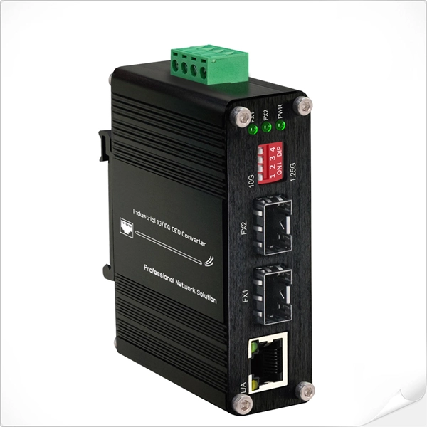
This application note explains how Site Master is used to measure cable insertion loss with different test methods and how to predict the maximum allowable cable insertion loss through manual calculations. Desktop Insertion Return Loss Tester with color screen has stable and reliable performance, which integrates stable light source, high-precision power meter, insertion loss meter and return loss meter into one multifunction instrument. Based on domestic customers'. Modern handheld analyzers, like the Keysight FieldFox Analysers, are designed specifically for cable and antenna testing (CAT), offering fast and accurate insertion loss testing across a wide frequency range. These tools are invaluable for both installation and maintenance, enabling field. Insertion loss is expressed in decibels or dB. The decibel is a logarithmic expression of the ratio of output voltage (voltage of the signal received at the end of the link) divided by input voltage (the voltage launched into the cable by the transmitter). 0 PCB transmission line losses in a PCB production environment. In wireless communication systems, the transmit and receive antennas are connected to the.
[PDF]
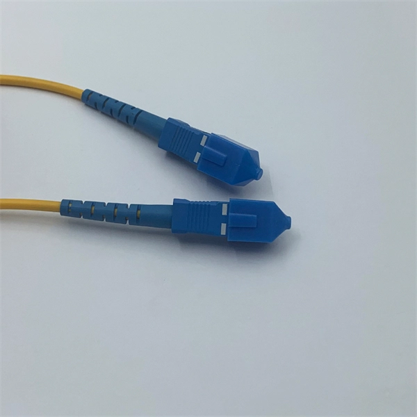
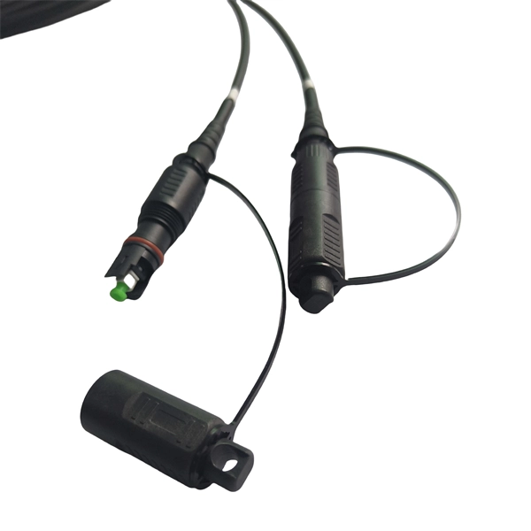
A fiber optic pigtail is a short length of optical fiber cable with a factory-terminated connector on one end and a bare, exposed fiber on the other. Executive Summary: A fiber optic pigtail is one of the most commonly specified yet least understood components in structured cabling. Get the wrong connector type, the wrong polish, or skip proper fusion splicing technique—and you're looking at elevated signal loss, increased back reflection, and a. According to Cambridge Dictionary, to splice means to “join the ends of something so that they become one piece. ” So in essence, fiber optic splicing is a process used to join two separate fiber optic cables together. There are numerous use cases for fiber optic splicing. Through splicing, fiber. Fiber optic joints or terminations are made two ways: 1) splices which create a permanent joint between the two fibers or 2) connectors that mate two fibers to create a temporary joint and/or connect the fiber to a piece of network gear. Either joining method must have three primary characteristics. Splicing allows you to restore or expand fiber networks while maintaining signal integrity. When done right, splicing ensures minimal loss and long-lasting performance. These terminations must be of the right style, installed in a.
[PDF]
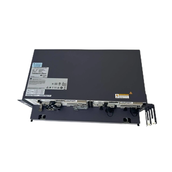
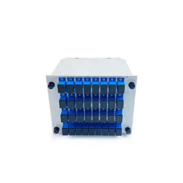
The devices has a wide pass band, low insertion loss, high channel isolation and excellent environmental stability. Channel numbers can be as high as 40 (16) for 100 (200)GHZ systems in C band or in L band. They can be used in DWDM systems to perform a multiplexing or. Fiberdyne Labs offers Dense Wavelength Division Multiplexer (DWDM) Modules in a wide variety of formats. While Fiberdyne offers some models as "standard," we will also produce customized DWDM modules. Customization can include the number and selection of DWDM channels. Channel. AFL's DWDM LGX modules provide scalable wavelength management for new deployments and network upgrades, providing increased bandwidth over a single common fiber. Based on thin film filter technology, the device is less than one-third the size of traditional cascaded DWDMs of similar channel count. Modules can be installed in standard LGX chassis and are available with LC bulkheads in select. All parameters are for device without connectors 2. Special specifications can be customized according to customer requirements DWDM mux demux and optical modules for high-capacity fiber networks. 40/80-channel options, rack mount or LGX type, low insertion loss, high stability. Ideal for telecom.
[PDF]
For singlemode fiber, the loss is about 0. 5 dB per km for 1310 nm sources, 0. 5 dB/km at either wavelength for outside plant max per EIA/TIA 568)This roughly translates into a loss of 0. 1 dB per. ity check. The fiber optic link attenuation is tested using an optical loss test set (OLTS) or a light source and power meter (LSPM) Figure 1). This type of testing is the most accurate testing available and is the most accurate characterization of the fiber optic system's apability. The estimate, called a "loss budget" is calculated using typical component losses for. Many solutions for 100 Gbit/s Ethernet have proposed to use CWDM to carry the multiple lanes over separate wavelengths on a single fibre. The presentation from Monterey anslow_01_0107. wavelength to justify the choice of CWDM channels to be analysed. It was. This document outlines the specifications for a single-mode optical fiber and cable designed for use around the 1310 nm zero-dispersion wavelength, suitable for both the 1310 nm and 1550 nm regions, and compatible with analogue and digital transmission. The acceptable dB loss for single mode fiber can vary depending on several factors. Measured in decibels (dB), insertion loss is the reduction in signal power that happens along any length of cable for any type of transmission. The longer the cable, the more a signal is reduced (or attenuated) by the time it reaches the far end. In addition to length, events that cause reflections.
[PDF]
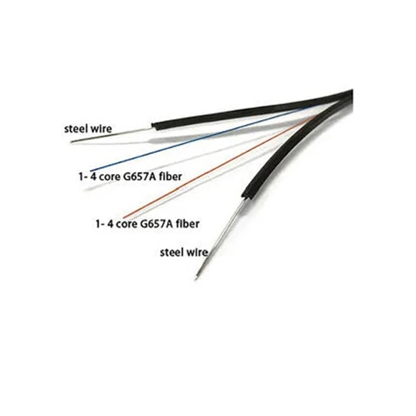
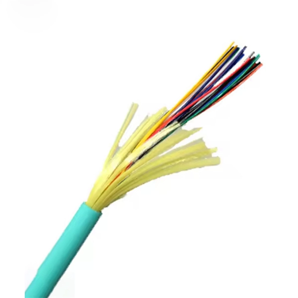
Built with OS2 singlemode fiber, it ensures ultra-low insertion loss and excellent return loss, providing stable transmission over long distances. unk cables connect central patching locations to zones or pods. Available terminated with both modular (MPO) and discrete connectors, these trun s are custom built in any length to meet specific applications. An optional pulling eye, installed on the first end, rotects fiber connectors on 12-. The OS2 Singlemode Simplex LC/SC/FC/ST Armored Fiber Optic Pigtail from Fiber-Life is designed for reliable and durable fiber terminations in demanding network environments. GYTA53 Double-Layer Armored Stranded Structure, Customizable 4-288 Fiber Cores. Fully compatible with mainstream devices worldwide, precisely matching single-mode optical fibers, and enabling rapid project implementation. This reliable fiber pigtail cable comes with a pre-terminated connector on one end—ready for immediate. Armored pigtails from FiberZON. com - worldwide supplier in fiber optic solutions, optical network, FTTx, fiber testing, fiber cables & tools.
[PDF]
ShowMeCables offers a wide selection of LMR-600® thick low loss cables for long-distance runs. These LMR-600 cables are designed with flexibility, low loss and RF shielding with options such as ultra-flex, weatherproof and fire retardant rating for safe indoor, outdoor, or direct. TC-240-FM-X 3190-2891 <1. N Male Straight Plug 3. 35:1 (6) Hex/Knurl Solder Crimp A/G 1. Since 1975 delivering the world the best copper and copper alloy products to build a more connected, clean and efficient planet. is a Peruvian manufacturer that specializes in the design and production of electrical cables and conductors made from copper and aluminum for low and medium voltage applications. These. Check each product page for other buying options. Alligator Clips Electrical with Wires UL1015/18AWG, 6 Colors Jumper Test Leads Set, 1. Clips Soldered with Wires- EDGELEC Need help?. Our wire and cables have been helping real, hardworking pros on the job for more than 45 years. Their success is our success. Direct Wire is widely known as the market leader for highly durable and versatile cables and assemblies manufactured to stringent U. and international standards.
[PDF]
Attenuation is the natural loss of signal power over distance. This is inherent in all fiber types and happens even under ideal conditions. Factors such as wavelength and fiber quality influence attenuation. At shorter wavelengths like 850nm, attenuation is higher, especially in. To be able to judge whether a fiber optic cable plant is good, one does a insertion loss test with a light source and power meter and compares that to an estimate of what is a reasonable loss for that cable plant. The estimate, called a "loss budget" is calculated using typical component losses for. A significant signal loss in the optical fiber can cause unreliable transmission. How can we know the value of losses on the fiber link? Read on, this post will teach you how to calculate the losses in optical fiber and judge the fiber link performance. What is optical fiber loss? Fiber loss can be. At TREND Networks, we are frequently asked how much loss is allowed when conducting testing on fiber optic cabling. So how do you determine acceptable loss? When testing fiber optic cabling, determining acceptable loss is. Understanding fiber loss is vital in maintaining a reliable, efficient network. While some loss is expected, excessive or unexpected loss can lead to poor performance, network. Optical fiber loss is a term for signal loss affecting transmission reliability. So how is the fiber attenuation calculation? 1, ODN full attenuation accounting: According to the worst value.
[PDF]
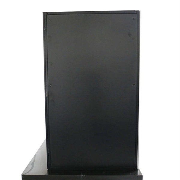
Fiber optic splicing metal box for 8 adaptors SC simplex, LC duplex or E2000. Wall mounting enabled. All products' documentation is published in PDF (Portable Document Format), which requires Adobe Reader (ver. 5 and newer) software for viewing. Though we pay utmost attention, we cannot guarantee. Every payment you make on Alibaba. com is secured with strict SSL encryption and PCI DSS data protection protocols Claim a refund if your order doesn't ship, is missing, or arrives with product issues. The HAILE 8 Optical Fiber Termination Box P1-8-FC is an essential fiber optic distribution frame designed to manage and protect fiber optic cables in various networking environments. This termination box is equipped with 8 ports that support FC connectors, making it ideal for high-performance. Fiberlink provides fiber optic splice box products for FTTH solution, including fiber terminal box, fiber splice enclosure, optical distribution box. FBR-11607 Fiber-Optic Distribution Box, 8-Core is a high quality product by Bud Industries used for electronic enclosure applications.
[PDF]
On average, a single fusion splice can take anywhere from 10 to 30 minutes, including preparation and testing. The answer isn't always straightforward, as it depends on various factors, including the type of fiber, the splicing method, and the level of expertise of the technician. Before we dive into the timeline, it's essential to understand the splicing process itself. Fiber splicing involves several. Fusion splicing refers to a method of joining two optic fibers together by means of heat, often an electric arc, which fuses the glass ends. It is the technique that has the least insertion loss and almost no back reflection, hence ensuring strong connections over a long period. A welding machine. This is typically done when the cable length is insufficient or when the fiber network is damaged and needs restoration. Unlike connectors, which are used for temporary joints, splicing creates a permanent, low-loss connection. This process is essential in telecommunications for extending network reach or repairing damaged sections without replacing entire cables. Splicing preserves the integrity and efficiency of the fiber optic network, offering a cost-effective solution for. A chart developed by Fiber Optic Association master instructor Joe Botha helps technicians calculate the amount of time it will take to conduct a fusion-splcing project. The FOA mentioned the chart in its November 2011 newsletter, stating, "We've been asked many times, 'How long does it take to.
[PDF]
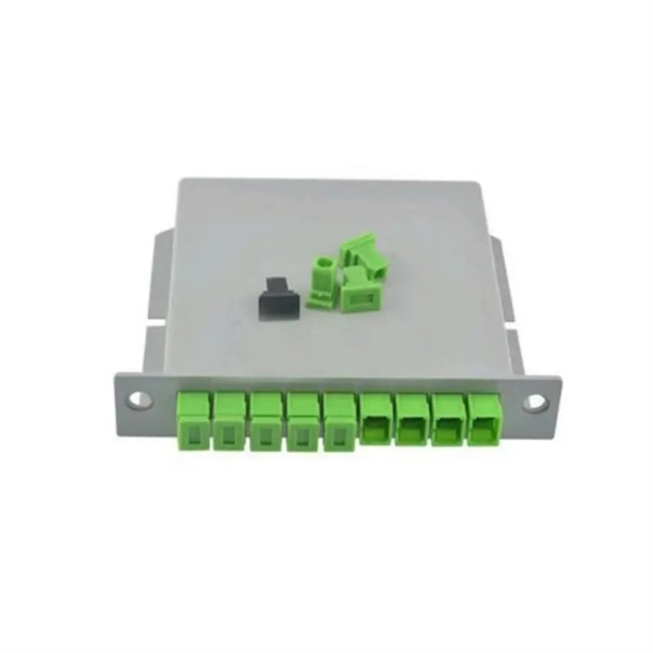
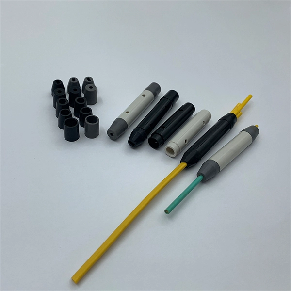
Optical fiber cold splice technology is based on the use of mechanical connectors to join two fiber-optic cables. These connectors are designed to align and join the fibers together in a precise and secure manner. This guide covers everything: what fiber optic pigtails are, how they differ from patch cords, which connector and polish type to specify, how to choose between mechanical and fusion splicing, and the real-world applications where pigtails are the right call. The connectors used in cold. Most fibers can be mechanically stripped without the aid of chemicals or heat. The recommended cleaning solvent for connectors and tools is isopropyl alcohol (reagent grade, 99% or beter). Do not use acetone for cleaning. They directly affect insertion loss, return loss, reliability, and long-term network stability. In this guide, we break down the most common optical fiber. In this beginner-friendly guide, we'll explain what it is, why the “APC” matters, the different types you can buy, how to select the right model, and how to install and test it correctly. What is an SC/APC Fiber Optic Adapter? An SC/APC fiber optic adapter is a passive mechanical interface used to. FASTConnect® field-installable connectors are factory pre-polished connectors that completely eliminate the need for hand polishing in the field. Proven mechanical splice technology ensuring precision fiber alignment, a factory pre-cleaved fiber stub and a proprietary index-matching gel combine to.
[PDF]
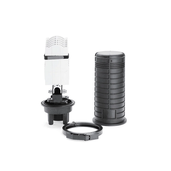
A splice box (also known as splice distributor) is a housing in which fiber optic cables begin or end. Fiber optics are fanned out in splice boxes that are situated at the end of fiber optic transmission paths. It typically consists of two parts: an outer housing and an internal structure. The main components of a splice box are the splice cassette that picks up the fibers and. The fiber optic dome splice closure is well-suited for splicing, distributing variable optical cables, and splitting. The solid box shell and the main structure are built to withstand harsh environments. The dome closure also protects fiber optic cables from vibration, impact, stretching, twisting. Home » Professional Insights » Fiber Optic Splice Closure: A Complete Guide to Types, Structure, Applications, and Selection In real fiber optic networks, cables are rarely installed as one continuous, uninterrupted length. Along transmission routes—whether in access networks, metro networks, or. Big space for managing pigtails or splitters. The 12 Port Fiber Distribution Box can connect up to 2 optical cables, providing space for distributors and 12 fuses. It is equipped with 12 SC adapters and can work in outdoor environments. Data communication networks. Horizontal fiber optic splice closures, also known as optical cable splice boxes, play an important role in the communications industry. It is a must-have device in the construction of optical cable line projects.
[PDF]
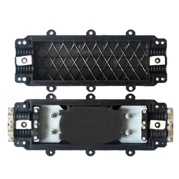
OPGW cable joint box installation involves several key stages: selecting the appropriate location, preparing both the cable and the joint box, splicing fibers, and sealing the joint box properly. Adhering to these steps ensures optimal performance and longevity of the telecommunications system. Optical fiber junction boxes are essential components in outdoor optical fiber cable installations. In this article, we will discuss the necessary steps and best practices. The Indoor/Outdoor Splice Box is a wall-mounted, indoor/outdoor fiber splice enclosure for centralized splice-only applications. These boxes are well suited as optical cable splice collection points for MDU (Multi-Dwelling Unit) residential fiber network applications, MTU (Multi-Tenant Unit). The installation of an optical cable junction box is crucial in ensuring the integrity and performance of optical networks. As we enter 2024, adhering to best practices not only enhances system reliability but also mitigates potential issues that can affect customer experiences. Installing a fiber optic splice closure efficiently and effectively requires attention to detail and. AFL's SB01 splice enclosure provides protection from all types of elements. From weather to bullets, the iron and steel construction requires no additional protective covering. Furnished with four plugged cable ports (2 aluminum and 2 plastic) for either All-Dielectric Self-Supporting (ADSS) or.
[PDF]