In this article, you will learn the step-by-step process of testing your solar panels using a multimeter. We will cover the essential tools you need, the specific measurements to take, and how to interpret the results. By the end of this guide, you will be equipped with the knowledge to diagnose. Solar panels are usually tested under standard conditions using a light source that mimics the light from the sun on a clear day. You can use the following method if you want to test your solar panel under standard conditions. Testing solar panels is easy with a multimeter! To test the current. Your multimeter is your best friend when testing solar panels. You can use it to check: Here's how: Multimeter — I recommend getting one that is auto-ranging. Also, a simple voltmeter won't work here. You need a multimeter that can measure both volts and amps. Locate the open circuit voltage. Learning to test a solar panel with a multimeter is an investment in your knowledge and ability to manage your own solar energy system or provide valuable services in the growing solar industry. Measure Voc (open circuit voltage) — if it reads 0V, the panel or wiring is dead. If it reads 60–80 % of rated, a bypass diode has failed. Perfect for DIY solar builders, RV owners, o. more Audio tracks for some languages.
[PDF]
Please view our full RLH price list and contact us at info@fiberopticlink. com if you have any questions or special project needs. A fiber optic distribution panel (also known as a fiber distribution frame or FDF) serves as a centralized hub for managing, terminating, and distributing fiber optic cables in telecommunications and data networking systems. Fiber Adapter Panels fit all Multilink rack and wall mount Fiber Distribution Units. Panels are available in Simplex or Duplex adapter format. Patch panels are integral components of any network system. This equipment helps keep data systems and server rooms organized, functional and easily. Fiber optic patch panels are designed either to support direct termination or fusion splicing of the optical fibers. Fiber optic patch panels allow the optical splices of the fiber. Belden offers clean, simple, and lightweight Wall-Mount Panels within its DCX, FiberExpress (FX) UHD and ECX ecosystems. The versatile DCX Zero-U wall-mounting devices hold DCX cassettes and adapter frames and can be mounted under standard cable basket trays. The FX UHD and ECX modular platform of. UnitekFiber offers a wide variety of wall mounted fiber optic enclosures, including indoor fiber optic enclosures, outdoor rated fiber optic enclosures, plastic fiber optic enclosures or metal fiber optic enclosures. The wall mount fiber enclosure, also known as a wall mount fiber patch panel, is a.
[PDF]
In this video, we take you through the step-by-step installation of Optical Distribution Frames (ODF) and Optical Fiber Patch Panels—key components in setting up a robust fiber optic network. At Eman Communications, we specialize in delivering high-quality installations that ensure opt. more In. Fiber optic patch panels are mostly mounted in 19 inch relay racks, but they can also be mounted on freestanding rails, in cabinets and also on walls. The fiber optical patch panel is convenient for people to easily access the optical fiber cable in the panel. Keeping this page as a placeholder for now. Have any questions? Talk with us directly using LiveChat. An ODF is a centralized platform designed for terminating, cross-connecting, and managing optical fibers. It ensures fiber management is structured, minimizes signal loss, and provides accessibility for maintenance and future expansion. ODF Rack/Cabinet: Physical frame housing all terminations and. To connect fiber optic cables to a patch panel, users must follow a specific procedure that ensures proper connectivity and signal transmission. Here is a step-by-step guide on how to connect fiber optic cables to a patch panel. Step 1: Gather the Tools and Equipment The first step in connecting.
[PDF]
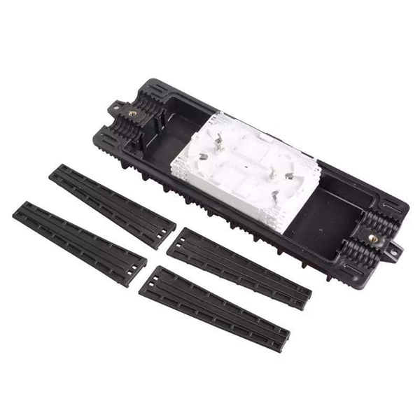
The panel can be pre-loaded completely with the required adapters or pre-loaded with pigtails and splice accessories. The tray is locked by 2 plastic latches and lowers to a 45 degree angle when fully extended. Installation and labeling are simple and easy. FS offers FHD® FAPs and FHU® 1U fibre patch panel with LC, SC, MTP®/MPO connectors in singlemode/multimode fibre to deploy medium for high-density fibre optic network applications. A patch panel or fibre distribution panel is a metal frame with pre- punched holes equally spaced horizontally along the front face. Unpopulated patch panels can be configured with bulkhead. A carefully selected range of fibre optic termination and patch panels from leading brands including Panduit, Canford and Speedway. A handy tool to for quickly finding a populated fibre connection panel that meets your requirements. Rack mounted fibre patch panels create a convenient, professional and easy access way to organise your fibre cables into a cabinet. Latest Optical Fibre Patch Panels for fibre installations.
[PDF]
Different solar panels will have information on the sticker on the back showing how to test. (1) Using a voltage meter, locate the open-circuit voltage (Voc) on the specifications label on the back of your solar panel. Write it down for late. Different solar panels will have information on the sticker on the back showing how to test. (1) Using a voltage meter, locate the open-circuit voltage (Voc) on the specifications label on the back of your solar panel. Write it down for later use. To measure the voltage of a DC circuit, you should prepare your multimeter by plugging the black probe. The short circuit current (Isc) on a circuit panel is located on the specifications label on the back of the panel. Record this number for later use. To prepare your multimeter to measure amps, move the red probe to the amperage terminal and set your multimeter to the amp setting (A). If your multimeter is not automatic-ranging, be sure to choose t. You can also measure the voltage of a photovoltaic panel (PV Current) by connecting it to a charge controller. It's possible to use a multimeter to determine how much current your solar panel is outputting, but you'll need an extra piece of equipment first. 1. Solar charge controller 2. Battery Plug the solar charge controller into the battery. Con.
[PDF]
This diagram highlights media converters, switches, and cable types. Also thanks to Init7 (for the great service), r/FiberOptics and FS for providing me with what I needed to get this setup going. If you find this article useful and you are considering Init7 as your provider you can use my referral code “20700408098” to get CHF 111. - off hardware and also support me. Keeping this page as a placeholder for now. Have any questions? Talk with us directly using LiveChat. A fiber optics network diagram illustrates how high-speed data travels from an internet service provider to end users. By using light signals, fiber optics provide faster speeds and better reliability than. MS Visio has long been the default choice for drafting fiber network diagrams, and with the right stencil libraries it can be used to draw everything from backbone routes to detailed patch panel layouts. When fiber techs look for visio fiber stencils, they are usually solving a very practical. Be among the first to receive important product updates, insights and news. Fiber optic cable is used for everything from demarcation point wiring to network signal distribution to video signal extension. Often, fiber enters the structure to a centralized rack or data room where it is connected to a modem. The modem connects to a network switch which connects each remote.
[PDF]
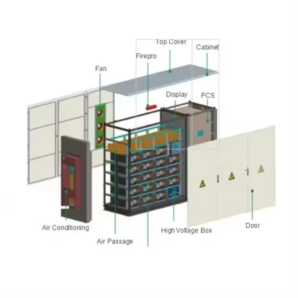
The main parts are the Miniature Circuit Breaker (MCB), Residual Current Device (RCD), busbars, and the main switch. Safe habits and checking the box often help stop electrical accidents. Learn about the main parts in a distribution box. These are MCBs, RCDs, busbars, and the main. A distribution box is a key part of electrical systems in buildings. Inside, you'll find parts like circuit breakers and fuses that protect the system from problems like overloads and short circuits. Today, electrical systems are essential for homes and industries. But what exactly is a power distribution box, and why is it so essential in our daily lives? The DB panel board controls the flow of electricity. Electrical systems power our homes, offices, and industrial facilities, but behind every reliable electrical setup lies a crucial component that often goes unnoticed: the distribution box. If you know. The internal structure of the distribution box is designed to safely distribute power from the main power source to multiple branch circuits. It provides convenience for protection, control and maintenance.
[PDF]
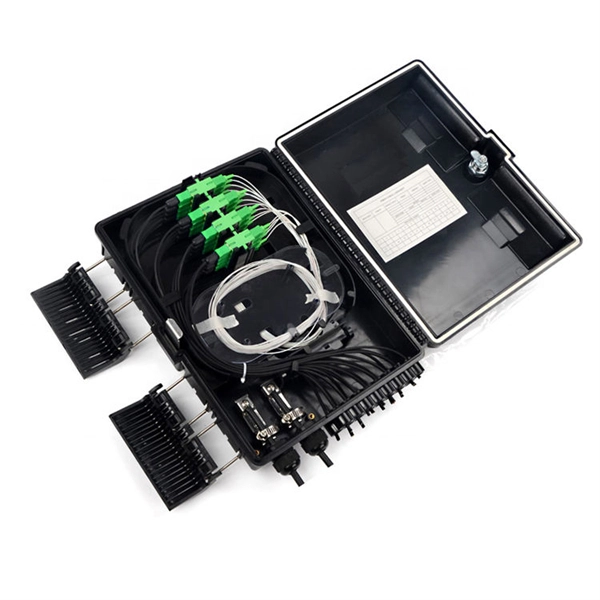
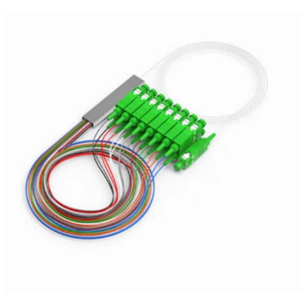
Fiber optic patch panels are enclosures that act as a distribution hub for fiber cable. A bulk (multi-strand) fiber cable enters the patch panel and then each fiber strand is separated into individual strands or pairs of strands. It acts as a hub for organizing splices and patch cords, streamlining fiber management and preserving signal integrity. These individual strands will then connect to electronic devices. A patch panel, including fiber patch panels and Ethernet patch panels, is a passive network device that centralizes, terminates, and organizes multiple copper or fiber cables. Serving as the interface between permanent cabling and active equipment, it provides clearly labeled ports that make. Structured cabling is a standardized system to help you organize and install the cables and hardware that connect your different devices to your network (including computers, servers, cameras, or any other smart gadgets). This article explores the structure, functionality, types, and benefits of fiber optic patch panels. What's the Fiber Optic Patch.
[PDF]
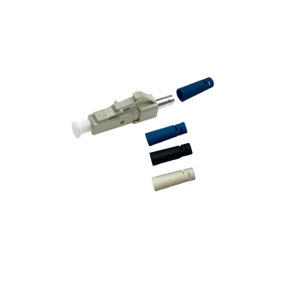
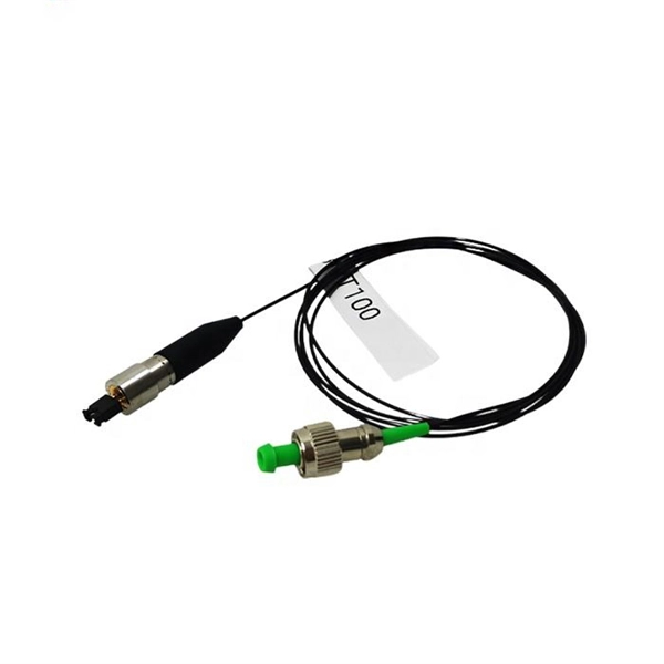
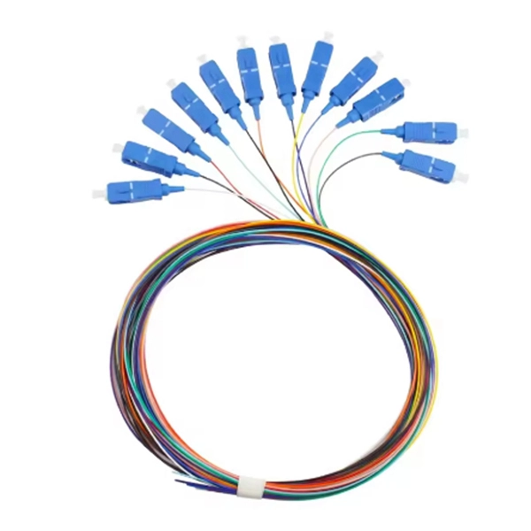
Mouser offers inventory, pricing, & datasheets for Duplex Fiber Optic Connectors. Check each product page for other buying options. QIANRENON LC Fiber Panel Mount Adapter LC Fiber Optic Connector Socket LC Fiber Coupler Module. XLR Panel/D-Panel Mount, for Fibre Optic Network LAN Integrated Cabling Need help?. Pricing (USD) Filter the results in the table by unit price based on your quantity. A tariff of 10% may be applied if shipping to the United States. A. Fiber Optic Connectors are the ends used to terminate optical fiber cable. The connector styles are DNP, ESCON, FC, FDDI, FSD, FSMA, LC, MPO, MT-RJ, MU, SC, SCRJ, SCRJ and Power Jack, SMA, ST, TNC, and VF-45. The mode options are multimode (OM1, OM2, OM3, OM4), POF, and Singlemode (OM1). These. High quality faceplates, RJ45 plugs, and copper, audio, video, and fiber optic modules from Molex, Leviton, CommScope, SignaMax, and more. COM supplies different types of fiber optic wall plates outlets, including angled ports fiber optic wall plate outlets. The angled opening provides a low profile and strain relief and allow fiber connectors and jumpers. Corning wall-plate outlet (WLL) is a highly configurable outlet product, available in both single- and double-gang configurations. It is designed for use within fiber-to-the-desk (FTTD) applications but may also be used to connect telephones and other peripherals to a network. A variety of fiber and.
[PDF]
You can test a photocoupler with a multimeter. This checks if its output changes when you power its input. This gives you the most accurate test results. This detailed guide will walk you through the process of testing an optocoupler using a multimeter, covering various scenarios and providing practical advice to ensure accurate results and avoid common pitfalls. We'll explore the underlying principles, delve into different testing methods, and. In this episode #0018 of Electronic Components Testing, we reveal how to test an optocoupler (optoisolator) using a digital multimeter step by step. This simple yet powerful technique will help you detect faulty optocouplers on circuit boards without desoldering them. Always. What are the methods to test optocoupler? The quality of the optocoupler can be determined by measuring the forward and reverse resistance of its internal diode and triode. Jotrin Electronics Limited will tell you that the reliable detection methods,as follows: 1. From basic circuit design to complex industrial systems, accurate optocoupler. Optocoupler is one type of ICs, It isolates input and output section by using optical technology this feature increase safety of circuit. Optocoupler has many part number, different part number has different output type so before checking it has to use part number to research with datasheet and.
[PDF]