Instead of fusing one fiber at a time, mass fusion splicing can fuse up to all 12 fibers in one ribbon at once. Many of today's cables with high fiber count involve subunits of 12 fibers each that can be quickly ribbonized. Fiber optic joints or terminations are made two ways: 1) splices which create a permanent joint between the two fibers or 2) connectors that mate two fibers to create a temporary joint and/or connect the fiber to a piece of network gear. Either joining method must have three primary characteristics. Fiber optic splicing is the process of seamlessly joining two single Splicing has a lower optical loss and back-reflection than other terminations, making it the ideal choice for maintaining signal integrity and reliability in fiber optic networks. There are numerous use cases for fiber optic splicing. Through splicing, fiber optic technicians can extend the length of the fiber to make it long enough for use in a required cable run. As. To begin, the standard definition of splicing in optical fiber is joining two fiber optic cables together. The other, more common, method of joining fibers is called termination or connectorization. Splicing is most commonly used in the field but has application in cable assembly houses.
[PDF]
A fusion splicer is a specialized device used to join two optical fibers end-to-end through the process of fusion. By aligning the fibers precisely and applying a controlled electric arc, the fusion splicer melts the ends of the fibers, creating a single, continuous fiber. Fusion splicers are essential for creating low-loss, high-performance fiber optic connections in telecom, FTTH, and data center applications. The best splicers offer core alignment, fast splice times, durable designs, and smart features like cloud syncing and automated calibration. This process minimizes. Fiber splicing is the process of permanently joining two fibers together. Unlike fiber connectors, which are designed for easy reconfiguration on cross-connect or patch panels. There are two types of fiber splicing – mechanical splicing and fusion splicing. It is the technique that has the least insertion loss and almost no back reflection, hence ensuring strong connections over a long period. Fiber optic splicers are.
[PDF]
Stimulated Brillouin scattering (SBS) is often an unwanted loss mechanism in both active and passive fibers. Highly multimode excitation of fibers has been proposed as a novel route toward efficient SBS suppression. Here, we develop a detailed, quantitative theory which confirms this proposal and. To keep a smooth output beam, most techniques for mitigating optical nonlinearities are restricted to single-mode fibers. Moving out of the single-mode paradigm, we show experimentally that wavefront-shaping of coherent input light that is incident on a highly multimode fiber can increase the power. In high power applications of multimode optical fibers such as high power beam delivery and optical phase conjugation, the estimation of critical power of stimulated Brillouin scattering is important. Nevertheless, the estimations have taken no account of mode dispersion effect to date. In this. Suppressing Stimulated Brillouin Scattering in Multimode Fiber Amplifier With High Beam Quality Via Full-Field Wavefront Shaping S.
[PDF]
A fiber pigtail is typically a fiber optic cable with one end factory pre-terminated fiber connector and the other exposed fiber. It is usually suitable for field termination using a mechanical or fusion splicer. Executive Summary: A fiber optic pigtail is one of the most commonly specified yet least understood components in structured cabling. Get the wrong connector type, the wrong polish, or skip proper fusion splicing technique—and you're looking at elevated signal loss, increased back reflection, and a. A fiber optic pigtail is a short length of optical fiber —typically 0. The connector end is polished and tested under factory conditions, ensuring low insertion loss and high return loss. The connector end can be linked directly to network equipment, while the exposed end can be spliced to another fiber optic cable. Compared with quick termination or epoxy and polish connections placed on the field. Fiber optic pigtails are short, single, or multi-strand pieces of optical fiber cables with a connector on one end and exposed fiber on the other end. This essential function of pigtail fiber is.
[PDF]
Multimode fiber has a larger core (typically 50 or 62. 5 microns) and can carry multiple light signals, usually LEDS, at once. While that's great for short distances, those overlapping signals can bump into each other and cause distortion over longer distances. This design makes them ideal for short to medium-distance communication and cost-effective installations. What is Multimode Fiber Cable? Multimode fiber (MMF) is an optical fiber designed to carry multiple light propagation paths—or. Multi-mode optical fiber is a type of optical fiber mostly used for communication over short distances, such as within a building or on a campus. Multi-mode links can be used for data rates up to 800 Gbit/s. Single-mode fibers allow only a single mode of light to propagate through the core, resulting in less signal dispersion and higher bandwidth capabilities. Single-mode fiber, as the name suggests, transmits a single light mode. It has a narrow core diameter of 8-10 microns and uses a laser or. They are typically more expensive than multimode cables, though, and there are different types of single and multimode fiber optic cables to consider, making the single mode vs. To help you decide on the type of cable you need for your.
[PDF]
Dual fiber modules use two fibers. They are easier to set up and give steady communication. They use a thin fiber core. They cost less and are. IntroductionEngineers, purchasing managers and installers often see the terms Transceiver, optical module and fiber optic module used interchangeably — and that causes confusion. This article answers the question directly and precisely: what each term usually means, where they overlap, and what. Optical modules and fiber optic transceivers are both essential components in fiber optic communication systems. Optical module: belongs to a. However, there are still many things that need to be paid attention to about how to link the optical fiber and the optical module. An optical module is a functional module, or an accessory. It is a passive device that cannot be used alone. It can only be used in switches and devices with optical.
[PDF]
BMPT-62 (sometimes called Algerian Terminator in reference to the BMPT Terminator) – A fire support vehicle developed from leftover T-62 tanks and Berezhok turrets. The vehicle was presented at the 60th anniversary parade of Algeria's independence. the BMPT-62 is a fire support fighting vehicle specific to Algeria, often nicknamed locally "Mini Terminator". This is not a standard Sovie. TypeFire Support Combat Vehicle (Tank support combat vehicle) · Place of originIn service2010s–presentUsed byDevelopmentThe concept of the BMPT-62 was born out of 's desire to have a tank support vehicle similar to the Russian "Terminator" (which Algeria also has in active service). The development was carried out. The concept of converting retired T-62 main battle tanks into fire support vehicles emerged from the Algerian Army's logistics and upgrade experience with the Russian-made Berezhok turret system. Algerian engineers.
[PDF]
In, a single-mode optical fiber, also known as fundamental- or mono-mode, is an designed to carry only a single of light - the. Modes are the possible solutions o. In 1961, while working at American Optical published a comprehensive theoretical description of single mode fibers in the. At the Corn.
[PDF]
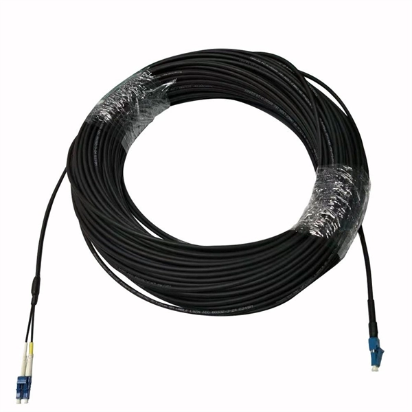
The drop cable connects your home, the patch panel organizes the network, the splice keeps connections seamless, and the optical splitter shares the signal with your neighbors. The fiber drop cable is what makes a true fiber-to-the-home (FTTH) connection possible. It's the final link in the chain that ensures you're getting the full, unfiltered power of fiber internet, not a mix of fiber and older technology. From the street to your living room, every piece of the fiber. To begin, the standard definition of splicing in optical fiber is joining two fiber optic cables together. The other, more common, method of joining fibers is called termination or connectorization. Splicing is most commonly used in the field but has application in cable assembly houses. Infield. In many applications of fiber optics, it is necessary to connect fiber ends (terminations) in some way such that light from one fiber can get into the other fiber without losing too much of its optical power. This creates a permanent and low-loss connection. Both techniques have their advantages and are suited for different applications, but understanding which method to use can greatly impact the network's. Many installations involve splitting the fibers in a cable or dropping a small fiber count cable from a large backbone cable. Backbone cables of 144-288 fibers are common and larger ones are becoming more common too. Drop cables are often only 2-12 fibers, meaning most fibers are continuing.
[PDF]

652 single-mode fiber, G. 655 single-mode fiber has lower dispersion in C-band (1530nm~1565nm), so the function of the optical amplifier in this band can be maximized, and the core area of the fiber is larger. Compared with G. 652B single-mode fibers are not suitable for wavelength division multiplexing applications because of their water absorption characteristics. 655 fiber is designed to reduce the effects of chromatic dispersion and PMD compared to G. It has significantly lower dispersion characteristics, enabling longer transmission distances and higher data rates. Non-Zero Dispersion Shifted (NZDS): G. 655 fiber. G652 is currently the most popularly adopted single mode fiber, for which G652 is defined as Standard SMF. It has G652A, B, C and D four versions. G652A and B have a zero dispersion wavelength point at 1310 nm, which makes it a natural fit for operation in the 1310 nm band. However, they are not. Among them, G. D fibers possess higher performance than G. The more recent variants, G. D, feature a reduced water peak that allows them to be used in the wavelength region between 1310.
[PDF]

To connect an optical cable to an SFP module, use the appropriate patch cord (e., LC-LC, SC-LC, etc. The patch cord must match the fibre type – single-mode or multi-mode. Once connected, verify that the port activity indicator is on and run diagnostic commands to check the. Small Form-factor Pluggable modules (SFP module) are the workhorses of modern network connectivity, enabling flexible fiber optic or copper links between switches, routers, firewalls, and servers. Whether you're upgrading bandwidth, replacing a faulty unit, or reconfiguring your topology, knowing. Connecting your fiber optic cable to an SFP (Small Form-factor Pluggable) module can seem daunting if you're unfamiliar with networking hardware. However, with a bit of guidance, the process is straightforward. Remove the dust caps from the SFP module and the fiber optic cable. Today, we will discuss the best methods to connect SFP to fiber optic patch cables. To connect a fiber optic cable to SFP optical module, first ensure the SFP is fully inserted into the network port until it "clicks", then remove the dust caps from both the SFP and the LC fiber optic connector. Laser Compliance The fiber-optic SFP+ / SFP28 modules contain a laser that is classified as a “Class 1 Laser Product” in accordance with US FDA regulations and the IEC 60825-1. The product does not emit hazardous laser radiation. The module is fully seated when you hear a click. (SFP+ and SFP28.
[PDF]
Connecting a multi-mode SFP to single-mode fiber creates a major signal mismatch. A small portion of the transmitted light gets captured. This leads to high attenuation and frequent link drops. I suggest you avoid such setups. Use them if essential and with proper mode conditioning. But what happens when you need to connect an existing multi-mode campus network to a new single-mode service provider link? You can't just splice them together. This is where fiber conversion comes in. This guide will break down the professional methods to achieve seamless single-mode to multi-mode. A fiber optic cable or optical fiber cable is a medium used for transmitting optical signals from one place to another. It consists of a strand of glass fibers inside an insulated casing. Fiber optic cable comprises a core, cladding, and a buffer. I've seen people use a single-mode. But not all fiber cables are created equal: multimode (MM) and single mode (SM) fibers are the two primary types, each engineered for specific use cases, from short-range data center connections to transcontinental telecom backbones. This type of patch cord helps to transfer the single mode signal into a multimode signal by aligning the two different types of fibers. However, it's important to note that this method may have. Multimode fiber cabling is used for indoor, short distance applications and single-mode fiber cabling is used for outdoor, long distance application.
[PDF]