Instead of fusing one fiber at a time, mass fusion splicing can fuse up to all 12 fibers in one ribbon at once. Many of today's cables with high fiber count involve subunits of 12 fibers each that can be quickly ribbonized. Fiber optic joints or terminations are made two ways: 1) splices which create a permanent joint between the two fibers or 2) connectors that mate two fibers to create a temporary joint and/or connect the fiber to a piece of network gear. Either joining method must have three primary characteristics. Fiber optic splicing is the process of seamlessly joining two single Splicing has a lower optical loss and back-reflection than other terminations, making it the ideal choice for maintaining signal integrity and reliability in fiber optic networks. There are numerous use cases for fiber optic splicing. Through splicing, fiber optic technicians can extend the length of the fiber to make it long enough for use in a required cable run. As. To begin, the standard definition of splicing in optical fiber is joining two fiber optic cables together. The other, more common, method of joining fibers is called termination or connectorization. Splicing is most commonly used in the field but has application in cable assembly houses.
[PDF]
A fiber pigtail is typically a fiber optic cable with one end factory pre-terminated fiber connector and the other exposed fiber. It is usually suitable for field termination using a mechanical or fusion splicer. Executive Summary: A fiber optic pigtail is one of the most commonly specified yet least understood components in structured cabling. Get the wrong connector type, the wrong polish, or skip proper fusion splicing technique—and you're looking at elevated signal loss, increased back reflection, and a. A fiber optic pigtail is a short length of optical fiber —typically 0. The connector end is polished and tested under factory conditions, ensuring low insertion loss and high return loss. The connector end can be linked directly to network equipment, while the exposed end can be spliced to another fiber optic cable. Compared with quick termination or epoxy and polish connections placed on the field. Fiber optic pigtails are short, single, or multi-strand pieces of optical fiber cables with a connector on one end and exposed fiber on the other end. This essential function of pigtail fiber is.
[PDF]
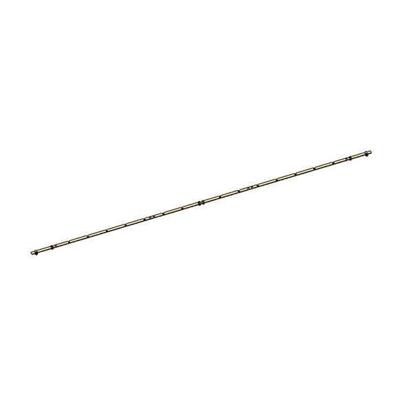
Factory terminated pigtails can easily be fusion or mechanically spliced to an existing fiber line. Custom lengths, connector combinations and. This 12-fiber optic pigtail is designed for efficient fusion splicing in structured cabling systems. It supports data centers, CATV, PON, WDM/DWDM multiplexing, FTTH, and voice services in ATM and SONET networks. With OS2 bend-insensitive fiber, it minimizes attenuation caused by bends or twists. ( Order Today, Ship before 05/01/2026 ) We supply LC/APC Single mode 12 Pack Multi Color Fiber Optic Pigtails with competitive price. We supply quality LC/APC Single mode Fiber Optic Pigtails are 12 packs that are 3 meters long with 900um outter jacket. Ideal for fusion splicing. We also offer. New to ADI? Become a Customer Please sign in to view pricing, availability, and to add to cart. Country of Origin: United States. Featuring LC style connectors, these pigtails are sold in a convenient 12 pack. FS 12 fibers pigtails with LC SC connectors feature color-coded or bunch design for various fiber splicing applications. 100% end-face, 3D interferometer, IL & RL tested. The LC APC 12 core bundle fiber optic pigtail consists of twelve individual fiber optic pigtails, each terminated with an LC APC connector on one end.
[PDF]
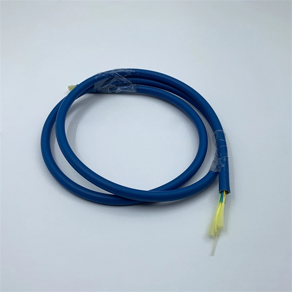
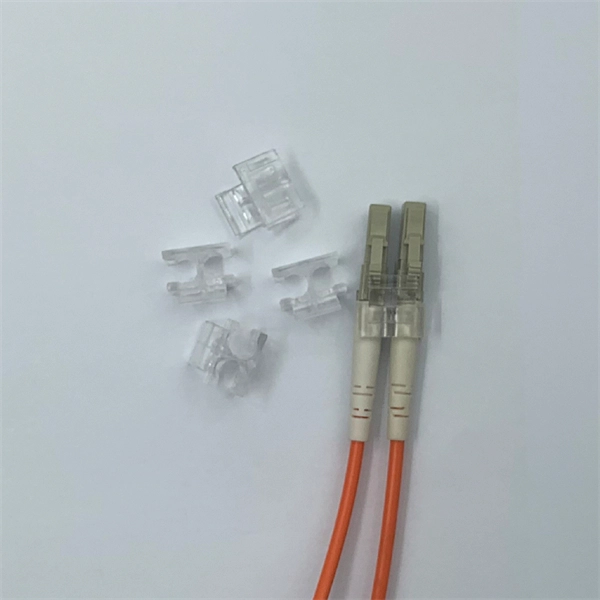
Multimode fiber offers the highly bandwidth at the fastest speed, and it gets to restrict transmission for shorter distance. Multi mode fiber cable is less expensive compare over single mode fiber. Due to its high power signal transmission capacity, multi mode fiber can support. Multimode fiber (MMF) is an optical fiber designed to carry multiple light propagation paths—or modes—simultaneously. This is made possible by its relatively large core diameter, typically 50 or 62. 5 microns, compared to the ~9-micron core in single-mode fiber. This characteristic enables them to transmit data at high speeds over relatively short distances, making them an essential component in various optical and photonic. Multi-mode optical fiber is a type of optical fiber mostly used for communication over short distances, such as within a building or on a campus. Multi-mode links can be used for data rates up to 800 Gbit/s. Most multimode fiber types used today are OM3/OM4 and OM5, but there are. Multi-mode fiber optics (MMF) play a crucial role in modern telecommunications and data networking, offering versatile solutions for high-speed data transmission over shorter distances. Here's why MMF is a preferred choice for various applications: Benefits of Multi-Mode Fiber Optics:.
[PDF]
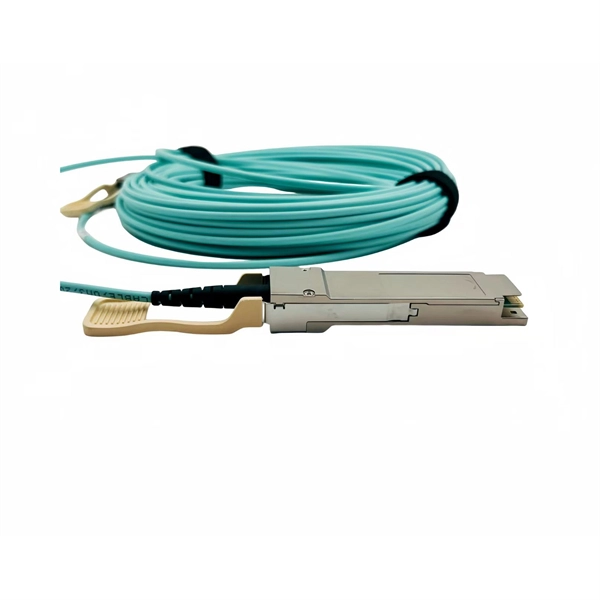
Dual fiber modules use two fibers. They are easier to set up and give steady communication. They use a thin fiber core. They cost less and are. IntroductionEngineers, purchasing managers and installers often see the terms Transceiver, optical module and fiber optic module used interchangeably — and that causes confusion. This article answers the question directly and precisely: what each term usually means, where they overlap, and what. Optical modules and fiber optic transceivers are both essential components in fiber optic communication systems. Optical module: belongs to a. However, there are still many things that need to be paid attention to about how to link the optical fiber and the optical module. An optical module is a functional module, or an accessory. It is a passive device that cannot be used alone. It can only be used in switches and devices with optical.
[PDF]
BMPT-62 (sometimes called Algerian Terminator in reference to the BMPT Terminator) – A fire support vehicle developed from leftover T-62 tanks and Berezhok turrets. The vehicle was presented at the 60th anniversary parade of Algeria's independence. the BMPT-62 is a fire support fighting vehicle specific to Algeria, often nicknamed locally "Mini Terminator". This is not a standard Sovie. TypeFire Support Combat Vehicle (Tank support combat vehicle) · Place of originIn service2010s–presentUsed byDevelopmentThe concept of the BMPT-62 was born out of 's desire to have a tank support vehicle similar to the Russian "Terminator" (which Algeria also has in active service). The development was carried out. The concept of converting retired T-62 main battle tanks into fire support vehicles emerged from the Algerian Army's logistics and upgrade experience with the Russian-made Berezhok turret system. Algerian engineers.
[PDF]

652 single-mode fiber, G. 655 single-mode fiber has lower dispersion in C-band (1530nm~1565nm), so the function of the optical amplifier in this band can be maximized, and the core area of the fiber is larger. Compared with G. 652B single-mode fibers are not suitable for wavelength division multiplexing applications because of their water absorption characteristics. 655 fiber is designed to reduce the effects of chromatic dispersion and PMD compared to G. It has significantly lower dispersion characteristics, enabling longer transmission distances and higher data rates. Non-Zero Dispersion Shifted (NZDS): G. 655 fiber. G652 is currently the most popularly adopted single mode fiber, for which G652 is defined as Standard SMF. It has G652A, B, C and D four versions. G652A and B have a zero dispersion wavelength point at 1310 nm, which makes it a natural fit for operation in the 1310 nm band. However, they are not. Among them, G. D fibers possess higher performance than G. The more recent variants, G. D, feature a reduced water peak that allows them to be used in the wavelength region between 1310.
[PDF]
Fiber optic cables can be run anywhere from 2 kilometers to over 100 kilometers without signal regeneration, depending on the cable type and application. Fiber optic cable transmission distance is determined by two primary physical factors that affect signal quality as light travels through the fiber medium. The greater the distance, the greater. In this blog, I will discuss the fiber optic cable distance, the effect factors, how to choose the right fiber optic cables, and how to compare the transmission distances of single-mode and multimode fiber optic cables. Single-mode fiber (SMF) supports distances up to 40-100+ kilometers for standard applications, while multimode fiber (MMF) is typically limited. Fiber optic cables are the backbone of modern communications, enabling high-speed data transfer over vast distances. Unlike traditional copper cables, fiber optic cables use light to transmit data, resulting in faster speeds and greater bandwidth capabilities. Chromatic dispersion This is a key factor affecting single mode fiber distance. While this technology offers higher speeds and longer distances than traditional copper wiring, physical limitations impose distance constraints. Light pulses degrade as they travel over long spans, primarily.
[PDF]
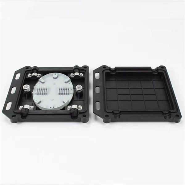
The drop cable connects your home, the patch panel organizes the network, the splice keeps connections seamless, and the optical splitter shares the signal with your neighbors. The fiber drop cable is what makes a true fiber-to-the-home (FTTH) connection possible. It's the final link in the chain that ensures you're getting the full, unfiltered power of fiber internet, not a mix of fiber and older technology. From the street to your living room, every piece of the fiber. To begin, the standard definition of splicing in optical fiber is joining two fiber optic cables together. The other, more common, method of joining fibers is called termination or connectorization. Splicing is most commonly used in the field but has application in cable assembly houses. Infield. In many applications of fiber optics, it is necessary to connect fiber ends (terminations) in some way such that light from one fiber can get into the other fiber without losing too much of its optical power. This creates a permanent and low-loss connection. Both techniques have their advantages and are suited for different applications, but understanding which method to use can greatly impact the network's. Many installations involve splitting the fibers in a cable or dropping a small fiber count cable from a large backbone cable. Backbone cables of 144-288 fibers are common and larger ones are becoming more common too. Drop cables are often only 2-12 fibers, meaning most fibers are continuing.
[PDF]
This paper discusses some practical aspects of implementing single-pole tripping schemes in transmission-line protection. Implementation and techniques will vary in the design of protective relaying systems that i.
[PDF]
Can two switches with fiber ports be directly connected through fiber ports? The answer is yes. The connection between two or more Ethernet switches in a certain way (Uplink port, etc. ) is. If you have multiple Ethernet switches that need to be connected over long distances, fiber is obviously a preferred choice. Moreover, when it comes to bandwidth, no currently available technology is better than single-mode fiber. ) is called the cascade. I need to connect a single 3750G - 48 ports switch to a single 2960 - 48 ports switch and it needs to be through a fiber. So, PCs connected to one switch would reach the PCs from the other switch. Well, I. Other than entry level network switches, most of today's network switches include one or more GiBC (Gigabit Converter) or SFP (Small Form-factor Pluggable) slots. SFP modules insert into these slots and and require two strands of fiber, typically duplex Using multi mode fiber (for runs under 1000. Fiber optic cabling is increasingly used to connect network switches and other datacom equipment, especially in long-distance and mission-critical applications. Fiber provides: Increased internet signal bandwidth. Most modern fiber-enabled network switches require an SFP transceiver module. I have an issue when connecting two switches with fiber. The switches connect as expected when in the same room and connected using 1m or 3m patch cables. This is where it gets strange.
[PDF]