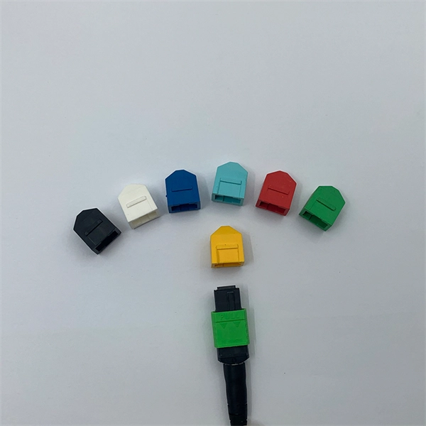
This report is a detailed and comprehensive analysis for global E2000 Connectors market. Both quantitative and qualitative analyses are presented by manufacturers, by region & country, by Type and by Application. Find advanced e2000 apc connector answers for quick and dependable data flow. Use modern technologies to improve connection for flawless communication. According to our (Global Info Research) latest study, the global E2000 Connectors market size was valued at US$ 191 million in 2024 and is forecast to a readjusted size of USD 318 million by 2031 with a CAGR of 7. 4% during review period. In this report, we will assess the current U. tariff. There are single mode E2000 UPC connector, single mode E2000 APC connector and multimode E2000 UPC connectors, and there are adapters to use with them accordingly. E2000 products include simplex and duplex versions. The E-2000 Connector Series is one of the few fiber optic connectors featuring a. E-2000® is an optical fiber plug connector, available for both single mode and multi-mode applications, featuring a spring-loaded shutter and dust-cap. Read More The connector lever is a durable, high-quality locking component designed specifically for SENKO E-2. It is widely used in data centers, telecommunications, and industrial networking due to its.
[PDF]
Explore a vast selection of robust and reliable connectors at Norwegian Electronic Supply AS. Designed for subsea and marine applications, our connectors ensure optimal performance. High-quality fiber cables, connectors, and assemblies for enterprise and infrastructure networks. Fiber connectivity engineered for shock, vibration, temperature extremes, and demanding field. T&G is a leading manufacturer and distributor of connectivity solutions including cables, harnesses, connectors, fiber optic boards, tools, and accessories. of our DNA and is incuded in everything we do. T&G is certified to EN9100 (AS9100), ISO9001 and ISO14001. our customers' needs. Hos oss finner du alt du trenger til ditt fibernett! Fiberworks is a specialized manufacturer in the fiber optic market, offering a variety of products and services. Several functions. One cable | Smart cable solutions. Our selection also includes Huber+Suhner's portfolio of their self-developed connectors for. The M Series connectors meet the highest standards of safety for deep immersion. It is currently used in many applications: from oil and gas industry service to renewable energy generation system and military submarines. The M Series feature a large range of shell styles, layouts or insulator.
[PDF]
EIA/TIA 568 B allows any fiber optic connector as long as it has a FOCIS (Fiber Optic Connector Intermateability Standard) document behind it. Fiber optic cold connection, also known as mechanical splicing, is a widely used method of connecting optical fibers in a network. Unlike fusion splicing, which uses heat to join two optical fibers together, cold connection uses mechanical means to create a stable and low-loss connection. Unlike fiber splicing, which is permanent, connectors allow for easy connection and disconnection of cables, making them ideal for maintenance and flexibility in. Fiber optic joints or terminations are made two ways: 1) splices which create a permanent joint between the two fibers or 2) connectors that mate two fibers to create a temporary joint and/or connect the fiber to a piece of network gear. These terminations must be of the right style, installed in a. Fiber termination refers to the process of preparing the end of a fiber optic cable to connect to another fiber, a device, or a network. Proper termination is essential for ensuring optimal performance, reducing signal loss, and maintaining the durability of the connection. Since the introduction of fiber optic technology decades ago, a variety of connector types have been.
[PDF]
Fiber optic connectors can be categorized according to different standards such as utilization, fiber count, fiber mode, and transmission method. They are also divided into single-mode and multimode types based on their distinct characteristics. The fiber connector types, sometimes referred to as terminations, link fiber optic cables together through terminals, switches, adapters, and patch panels, by bridging the gap between their internal glass fibers that transmit the data down the length of the cable. And based on the connector construction, LC connector also can be divided into LC duplex and simplex connector. a single mode fiber (SMF). And it has a “square shaped” connector body, which is the source of name “square connector”. Due. Fiber optic connectors, according to the different transmission media, can be divided into common silicon-based fiber single-mode and multimode connectors, and other such as plastic as the transmission medium of fiber optic connectors; according to the connector, structure form can be divided into:. A fiber optic connector is a mechanical device used to align and join optical fibers, enabling light to pass through with minimal loss. Simplex vs duplex fiber connectors, single mode vs multimode fiber connectors, what's the difference? This article will explain the above to you.
[PDF]
Learn how to choose the right fiber patch cord supplier by comparing price vs. quality, certifications, and delivery reliability. Back to Products & Services All Cable Assemblies Cable Assemblies Active Electrical Cable Solutions Active Optical Cables (AOC) AirBorn FOCuS Rugged Active Optical Cables Custom Cable Assembly Solutions Direct Attach Cable (DAC) Assemblies Fiber Optic Cable Assemblies HSAutoLink Interconnect System. Check each product page for other buying options. Need help?. Nano-Giga offers a wide range of fiber optic connectors and patch cords to suit your applications. The quick and professional support we receive from PTspeed ensures we always have what we need, when we need it. They're not just any supplier; they're an online supplier with robust in-stock. The fiber optic cable is used to connect or patch one optical device to another. Each end of the fiber optic cable has a connector that allows the installer to quickly connect or disconnect the cable as needed. They are very convenient. You will find the cable is. This guide will help you understand how to evaluate suppliers and make an informed decision when sourcing fiber optic patch cords for your projects — from FTTH deployments and Data Centers to Industrial Networks and Telecommunications Infrastructures. Tip: Many high-quality fiber patch cord.
[PDF]
Above finished grade or sidewalks, or from any platform or projection from which they might be reached. (If these areas are accessible to other than pedestrian traffic, then one of the other conditions applies). Ex: Parallel phase and neutral conductors can be installed in individual underground nonmetallic raceways (Phase A in raceway 1, Phase B in raceway 2, etc. ) as permitted by 300. 5 (I) Ex 2 if the installation complies with 300. Power conductors rated 1,000V or less can occupy the same. Switchboards and panelboards are often called “the guts” of a premises wiring system. Article 408 covers the requirements for switchboards and panelboards that control power and lighting circuits (Fig. For. According to the NEC, there are four types of branch circuits: 1. Appliance (2-wire circuit): Supply energy to one or more appliance outlets. They have not permanently connected luminaires unless these luminaires are part of the appliances – e., deep fryer, vacuum cleaner, toaster oven, coffee. The most common distribution primaries are f our-wire, multi-grounded systems: three-phase conductors plus a multigrounded neutral. Listed below are new code-related questions and.
[PDF]
Positive busbars, which collect all positive connections. Key Steps: When wiring a pair of 12V busbars, connect the positive terminal of each load to a stud on the positive busbar and their negative terminal to a stud on the negative busbar. 5' above batteries on inside of cockpit combing below decks. Install one new positive bus bar beside the negative one separated by about two inches 3. Positive and negative busbars are physically identical apart from the red/black colours used by some manufacturers to visually differentiate between. A Complete Guide to Battery Terminal Connector Types The store will not work correctly in the case when cookies are disabled. JavaScript seems to be disabled in your browser. For the best experience on our site, be sure to turn on Javascript in your browser. Skip to Content Blog Sign In Create an. This image illustrates a standard car battery with top post terminals and labeled connectors for the positive (+) and negative (–) ends, emphasizing safe and correct installation. A battery terminal connector is a fitting or clamp that attaches to a battery's terminal to connect a cable. In other. Both positive and negative terminals are the soul of the electrical system of the car, allowing the engine to start while keeping other components running. The catch? Mix-up or loose connection can cause electrical failure, drained batteries, and damage to wiring. This blog guides you how the two.
[PDF]
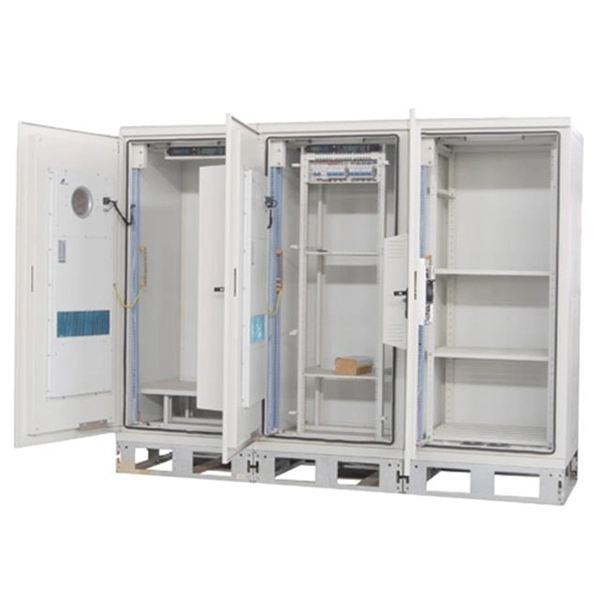
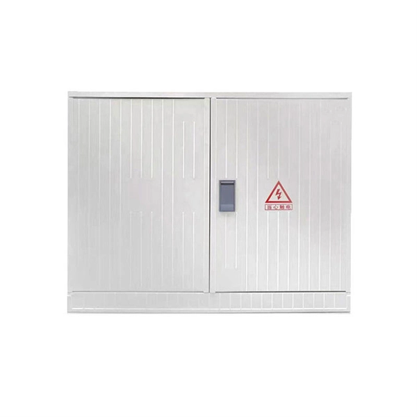
The XL-21 type low-voltage power distribution cabinet is an indoor fixed enclosed complete set of equipment that complies with IEC 60439-1 and GB 7251. It is specially designed for 50Hz AC power distribution systems with a rated voltage of 380V/660V and a rated current of. Standard Type (P Type): This version has a cabinet height of 1700mm or 1800mm and is designed for independent installation. It can be equipped with entry and exit holes at the top as required. Busbar Type (M Type): This version features a cabinet height of 1900mm or more, with a removable cover on. The Fulleto XL-21 series is an indoor, floor-standing power distribution cabinet engineered for excellence. It serves as the central hub for receiving and distributing electrical energy in low-voltage systems up to 380V. Designed for power plants, substations, industrial enterprises, and commercial. The XL-21 Power Distribution Box is used for power distribution, conversion, transmission, control, and on-site operations in low-voltage distribution systems. It is widely applied in power plants, substations, petroleum, chemical, metallurgy, machinery, and high-rise buildings. The XL-21 Power. The XL-21 type power distribution cabinet is a crucial component in electrical systems, designed to distribute power efficiently and safely across various industrial and commercial applications.
[PDF]
Encuentra conectores, patchcords, pigtails, fibras de lanzamiento, bandejas, paneles, cables, MPO, cajas de interconexión, mufas y más. Get access to all 22 remaining Fiber optic products suppliers with complete contact information, addresses, and business details. As of April, 2026, we have compiled data. The company specializes in providing high-speed internet and cable TV services, focusing on a network built entirely on fiber optic technology. This commitment to fiber optics enhances service quality and customer experience, offering faster connections with numerous benefits. Disfruta del mejor. We develop, manufacture, and distribute the best OEM telecommunications solutions for companies around the world. Leading telecom operators, ISPs, and utilities across the Americas choose our solutions, and many of our products are marketed as OEM solutions for third parties as well as under the. Are you looking for a professional and reliable fiber optic products manufacturer for your business? Are you still worried about how to find and select a best partner from so many fiber optic products manufacturers? Don't be afraid, Gcabling will help you. In this post, Gcabling, as a professional.
[PDF]