Learn how to choose the right fiber patch cord supplier by comparing price vs. quality, certifications, and delivery reliability. Back to Products & Services All Cable Assemblies Cable Assemblies Active Electrical Cable Solutions Active Optical Cables (AOC) AirBorn FOCuS Rugged Active Optical Cables Custom Cable Assembly Solutions Direct Attach Cable (DAC) Assemblies Fiber Optic Cable Assemblies HSAutoLink Interconnect System. Check each product page for other buying options. Need help?. Nano-Giga offers a wide range of fiber optic connectors and patch cords to suit your applications. The quick and professional support we receive from PTspeed ensures we always have what we need, when we need it. They're not just any supplier; they're an online supplier with robust in-stock. The fiber optic cable is used to connect or patch one optical device to another. Each end of the fiber optic cable has a connector that allows the installer to quickly connect or disconnect the cable as needed. They are very convenient. You will find the cable is. This guide will help you understand how to evaluate suppliers and make an informed decision when sourcing fiber optic patch cords for your projects — from FTTH deployments and Data Centers to Industrial Networks and Telecommunications Infrastructures. Tip: Many high-quality fiber patch cord.
[PDF]
There are currently three methods of looking inside a fiber optic connector: (1) Non-destructive X-ray (2) Lossless sonar (3) Destructive cross section These methods help engineers determine the causes and effects of fiber optic connector failures and monitor the connector assembly. There are currently three methods of looking inside a fiber optic connector: (1) Non-destructive X-ray (2) Lossless sonar (3) Destructive cross section These methods help engineers determine the causes and effects of fiber optic connector failures and monitor the connector assembly. Fiber Optic Center offers a unique cross-sectioning service to identify and isolate problems related to fiber optic terminations that would otherwise be invisible. All. There are two major uses for visual inspection of fiber optic connectors. Video microscopes should have ability to record images and some may have ability to analyze connector condition to standards. Look for dirt, contamination, scratches or any other problem. Since connectors are susceptible to damage that is not immediately obvious to the naked eye—the inspection phase is vital. When proceeding with the inspection of connectors, there are two main components to inspect: the connector itself and the ferrule. With the press of a single button, FOCIS Flex auto-focuses, captures and centers the end-face image, applies Pass/Fail rules, displays image and Pass/Fail results, saves results internally and/or wirelessly transfers data to a.
[PDF]

In this guide, we'll walk you through the entire process of preparing fiber optic cable for splicing and termination to fiber connectors. We'll explore the necessary tools, safety precautions, and step-by-step procedures for cable connectors, mechanical and. This article will guide you through the necessary tools, materials, and methods on how to connect fiber optic cables effectively, ensuring you achieve optimal performance from your fiber optic network. Have a network installation project? Fiber Optic Cables: The primary medium for your connections. There are many types of fiber optic connectors, including SC, LC, FC, ST, D4, MU, MT/MPO, etc. These connectors can be divided into single-mode and multi-mode fiber optic connectors according to their structure and purpose. Fiber optic connectors play an essential role in the realm of optical communication, enabling seamless connections between fiber optic cables. At the heart of any robust fiber optic network lies a crucial process: Preparing a fiber cable for termination of a connector or splice. Whether you're installing a new network, expanding an existing one, or. Fiber optic internet delivers blazing-fast speeds and reliable connectivity, making it a top choice for modern homes and businesses.
[PDF]
EIA/TIA 568 B allows any fiber optic connector as long as it has a FOCIS (Fiber Optic Connector Intermateability Standard) document behind it. Fiber optic cold connection, also known as mechanical splicing, is a widely used method of connecting optical fibers in a network. Unlike fusion splicing, which uses heat to join two optical fibers together, cold connection uses mechanical means to create a stable and low-loss connection. Unlike fiber splicing, which is permanent, connectors allow for easy connection and disconnection of cables, making them ideal for maintenance and flexibility in. Fiber optic joints or terminations are made two ways: 1) splices which create a permanent joint between the two fibers or 2) connectors that mate two fibers to create a temporary joint and/or connect the fiber to a piece of network gear. These terminations must be of the right style, installed in a. Fiber termination refers to the process of preparing the end of a fiber optic cable to connect to another fiber, a device, or a network. Proper termination is essential for ensuring optimal performance, reducing signal loss, and maintaining the durability of the connection. Since the introduction of fiber optic technology decades ago, a variety of connector types have been.
[PDF]
Fiber optic connectors can be categorized according to different standards such as utilization, fiber count, fiber mode, and transmission method. They are also divided into single-mode and multimode types based on their distinct characteristics. The fiber connector types, sometimes referred to as terminations, link fiber optic cables together through terminals, switches, adapters, and patch panels, by bridging the gap between their internal glass fibers that transmit the data down the length of the cable. And based on the connector construction, LC connector also can be divided into LC duplex and simplex connector. a single mode fiber (SMF). And it has a “square shaped” connector body, which is the source of name “square connector”. Due. Fiber optic connectors, according to the different transmission media, can be divided into common silicon-based fiber single-mode and multimode connectors, and other such as plastic as the transmission medium of fiber optic connectors; according to the connector, structure form can be divided into:. A fiber optic connector is a mechanical device used to align and join optical fibers, enabling light to pass through with minimal loss. Simplex vs duplex fiber connectors, single mode vs multimode fiber connectors, what's the difference? This article will explain the above to you.
[PDF]
Passive media components such as cables, cable splices, and connectors cause attenuation. Although attenuation is significantly lower for optical fiber than for other media, it still occurs in both multimode and single-mode transmissions. Two fundamental mechanisms cause attenuation inside the fiber itself: absorption and scattering. These are intrinsic to the glass, meaning they exist even in a perfectly manufactured, perfectly installed fiber. Scattering is the bigger factor at the wavelengths most networks use. The silica glass. Optical attenuation is the gradual loss of flux (light intensity) as an optical signal travels through a fiber. Measured in decibels (dB), it's the logarithmic ratio of the output power to the input power. Every network has a "loss budget". F iber optic networks rely on the efficient transmission of light signals to deliver high-speed data over long distances. However, various factors can cause signal degradation, leading to performance issues and reduced network reliability. You may see slower speeds and less steady connections when signal loss goes up. Things like impurities in the fiber core and reflections at the core-cladding edge cause this drop. This can be due to a variety of factors: scattering and absorption, intrinsic. Signal attenuation in fiber optics is a key concept in telecommunications. It affects how far a signal can travel without losing.
[PDF]
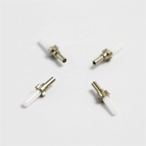
pigtails can be divided into single-mode (colored yellow) and multimode (colored orange) fiber. Multimode pigtails use 62.5/125 micron or 50/125 micron bulk multimode fiber cables and terminated them with multimode fiber optic c. pigtails can be divided into single-mode (colored yellow) and multimode (colored orange) fiber. Multimode pigtails use 62.5/125 micron or 50/125 micron bulk multimode fiber cables and terminated them with multimode fiber optic connectors at one end. 10G multimode fiber cables (OM3 or OM4) are also available in optic pigtails. The jacket color of 10. Fiber Optic Pigtails, In fiber optic cable installation, how cables are attached to the system is vital to the success of network. If done properly, optical signals would pass through the link with low attenuation and little return loss. pigtail offers an optimal way to joint optical fiber, which is used in 99% of single-mode applications. This pos. According to different types of pigtail cable connector terminated at the end, there are LC fiber pigtail, SC pigtail, ST pigtail, FC pigtail, fiber pigtail and so on. With different structures and appearance, each of them has their own advantages in different applications and systems. Let's go through some widely used ones. SC Pigtail: SC pigtail.
[PDF]
Encuentra conectores, patchcords, pigtails, fibras de lanzamiento, bandejas, paneles, cables, MPO, cajas de interconexión, mufas y más. Get access to all 22 remaining Fiber optic products suppliers with complete contact information, addresses, and business details. As of April, 2026, we have compiled data. The company specializes in providing high-speed internet and cable TV services, focusing on a network built entirely on fiber optic technology. This commitment to fiber optics enhances service quality and customer experience, offering faster connections with numerous benefits. Disfruta del mejor. We develop, manufacture, and distribute the best OEM telecommunications solutions for companies around the world. Leading telecom operators, ISPs, and utilities across the Americas choose our solutions, and many of our products are marketed as OEM solutions for third parties as well as under the. Are you looking for a professional and reliable fiber optic products manufacturer for your business? Are you still worried about how to find and select a best partner from so many fiber optic products manufacturers? Don't be afraid, Gcabling will help you. In this post, Gcabling, as a professional.
[PDF]
To find the best routerfor fiber internet, we used our expertise to select items based on key specs, such as speeds, coverage, wireless standards, security, weight, and additional features. We've also delve.
[PDF]