This article summarizes the latest fiber optic price data as of March 9, 2026, along with the recent timeline of price changes and the factors behind the surge. Before looking at the price, it is important to explain the source of the price data. What Factors Affect Fiber Optic Cable Pricing? Several factors influence how much you'll pay for fiber optic cables: Fiber Type and Count: Single-mode fiber typically costs $0. 50 per foot for the cable itself, while multimode fiber ranges from $0. Main cost drivers include cable grade (indoor vs outdoor, armoured), distance, and labor for trenching, splicing, and termination. This guide presents ranges in USD and practical price estimates to help. Fiber optic cables are essential components in today's broadband, FTTx, and data center networks. Many global fiber optic giants, such as Corning and. Let's be real: If you are wondering “how much does fiber optic cable cost” for your next project, you've probably seen quotes that make zero sense. One supplier in your inbox promises $0. 05 a foot, while a domestic distributor is asking for ten times that. You search “how much does fiber optic. CRU provides comprehensive, accurate and up-to-date price assessments and research reports for bare optical fibre across various key regional markets, combined with insights into the factors and events affecting markets.
[PDF]
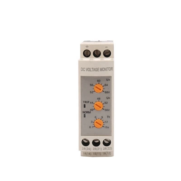
Standardized Dimensions: The rails have standardized dimensions, allowing easy integration of various modular equipment. The most commonly used rails are 35 mm wide, although other width options may also be available. Ease of Installation: DIN rails are designed for easy. At its core, a DIN rail is a standardized metal rail that provides a mounting system for all sorts of electrical and industrial control gear you'd find inside equipment racks, enclosures, and control panels. These rails, usually made from steel or aluminum, let you securely snap components like. This guide will provide you with the necessary information regarding the development of din rail and its standards, benefits, types, selection, and installation, including their specifications. What Are DIN Rails? 2. Lianjie - Blog - Electrical Equipment - What Is a DIN Rail? Mounting Guide for Electrical Panels 2026 What Is a DIN. DIN rails are standardized mounting rails designed for modular electrical equipment such as relays, automation devices, switches, circuit breakers, and other components to be mounted in electrical distribution boards. These products are typically made from cold rolled carbon steel sheet with a zinc-plated or chromated bright surface finish. Defined by standards such as IEC 60715 and EN 50022, the most common type is the 35mm “Top Hat” rail (TS35). It allows for the rapid, snap-on installation of modular.
[PDF]
We experimentally demonstrate 100 Gb/s bidirectional transmission over 40 km using a multi-wavelength bidirectional optical sub-assembly (BOSA) based on a single bidirectional multi-wavelength Mux/Demux. The Mux/Demux consists of an optical zig-zag glass block and thin film. A bidirectional SFP (BiDi SFP) provides an efficient solution by enabling data transmission and reception over a single strand of optical fiber. This physical-layer design instantly doubles existing cable plant capacity without requiring expensive new. BiDi optical modules can do this by utilizing full-duplex communication over a single fiber strand via two wavelengths. By reading this blog, you will understand how SFP BiDi technology allows you to save fiber, reduce costs, and simplify installation while enabling your network to increase. In the world of transceivers, BiDi stands for Bi-Directional. In terms of SFPs, BiDi transceivers transmit at one wavelength and receive at another. BiDi SFPs connect to a fiber cable using only one. A 1G BiDi transceiver solves these challenges through single-fiber bidirectional transmission, giving networks a more economical and efficient upgrade path.
[PDF]
7 meters) high makes it easily accessible without the need to bend or stretch excessively. This height also safeguards the box from potential water spills or accidental impacts. The proper installation of a distribution box involves placing it at the right height to ensure safety and convenience. This enclosure houses the circuit breakers, which are overcurrent protection devices designed to automatically shut off power during a fault or. However, the key to a safe and reliable system lies in proper installation. If it's done poorly, you risk short circuits, fire hazards, or system failure. Done right, it ensures safety, compliance, and long-lasting performance. In this guide, we'll break down everything you need to know to install. The International Standards of Practice for Inspecting Commercial Properties (ComSOP) states that the inspector should report on the lack of accessibility or working space for electrical panels and gear that would hamper their safe operation, maintenance, and inspection. Many jurisdictional and. Governed by NEC 110. 26, these rules define the minimum Spaces about electrical equipment necessary for workers to perform tasks like inspection, maintenance, and replacement safely. Note to paragraph (b): American National Standard National Electrical Safety Code, ANSI/IEEE C2-2012 contains.
[PDF]
Explosion-proof electrical distribution boxes are essential for safety in hazardous environments. These specialized enclosures are built to contain internal explosions and stop the ignition of flammable materials. In this article, we will explore three key aspects:. Explosion-proof enclosures are used by such facilities to ensure the safe housing of electrical components that could cause a spark and ignite these gases in the atmosphere. What Is An Explosion Proof Box or Enclosure? They are a cast aluminum or iron box that can withstand a heavy-duty explosion. The Code of Federal Regulations (CFR) is the official legal print publication containing the codification of the general and permanent rules published in the Federal Register by the departments and agencies of the Federal Government. In this blog post, MINMILE, as high quality explosion proof control boxes manufacturer, will share the importance of explosion proof distribution boxes in. For electricians, engineers, and safety managers working in petrochemical plants, refineries, and manufacturing facilities, selecting the right explosion proof junction box ensures compliance, reliability, and peace of mind. Need Certified Explosion-Proof Junction Boxes? Get ATEX/IECEx options for.
[PDF]
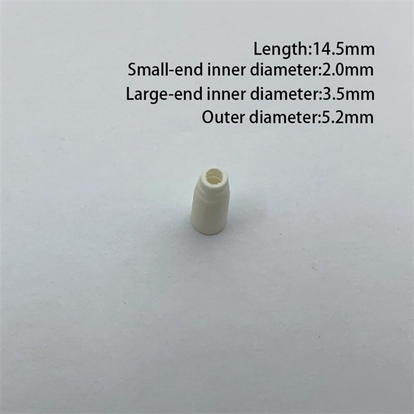
A2: According to EIA/TIA-598, the fiber optic cable color code defines the jacket color codes for different fiber types (SMF or MMF). Fiber optic color codes provide the essential identification framework that enables fiber technicians and network professionals to manage complex optical network installations efficiently. This standardized fiber optic color coding system helps prevent costly connection errors while dramatically. Understanding fiber‑optic color codes is essential for any technician tasked with installing, maintaining, or troubleshooting modern fiber networks. By adopting the TIA/EIA‑598C standard, you gain a universal “language” of colors that speeds identification, reduces miswiring, and enhances safety. The TIA-598-D standard defines a standardized color-coding system that engineers and technicians rely on to identify different types of fiber optic cables, connectors, and individual fibers. Designed for durability and reliability, the sleeves are constructed with an inner EVA meltable adhesive tube, and a polyolefin heat shrink outer tube. The strength member within the sleeve is made of. Color codes are used in fiber optics to identify fibers, cables and connectors. This coding system is the EIA/TIA-598 standard developed by the Electronic Industries Alliance (EIA) and the Telecommunications Industry.
[PDF]
Knowing when to use which color code can help you save time and prevent mistakes from occurring on the job. You'll likely need to use a tray cable with the E-1 color code if you're working on an electrical or utility application. When the project is n. Knowing when to use which color code can help you save time and prevent mistakes from occurring on the job. You'll likely need to use a tray cable with the E-1 color code if you're working on an electrical or utility application. When the project is not NEC-applicable, E-1 is OK to use. Locations where you'll likely encounter this color scheme incl. Based on the color combinations you see, you'll be able to determine what the wire is being used for. If you were to cut a cross-section of Kris-Tech wire and look at it head-on, you'd see a series of colored conductors arranged in a circle around the main conductor. Depending on which end of the cable you're looking at, you can read the colors clo. No matter the job type, rest assured there's a tray cable engineered to fit the job. Kris-Tech is ready for your next job with UL 1277 certified vinyl nylon tray cable (VNTC) and cross-linked polyethylene tray cable(XPTC). Whether you need some tray cable color-coded to meet NEC guidelines or want it custom-colored to match your preferences, Kris-T.
[PDF]
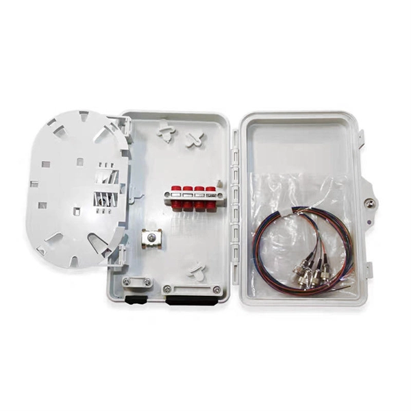
This guide reveals the secrets to fusion splicing with little fluff—just proven, straightforward techniques refined from years of work in the field. In this guide, you will find a chronological description of the fusion splicing process, the principal technical standards, and answers to the real-life questions network engineers and procurement teams may have. The guide provides the complete workflow, covering safety precautions, tool selection, fiber preparation, fusion operation, quality control, and. Summary: Fiber color codes, defined by the TIA-598-C standard, help technicians quickly identify individual fibers, buffer tubes, and connectors in multi-strand cables. Using proper color coding makes installation easier, speeds up troubleshooting, reduces downtime, and supports future network. When a tech opens a fiber optic cable to prepare it for splicing, they will find a colorful bundle of buffer tubes as on this armored cable. The colors of the buffer tubes and likewise the fibers in the tubes provide the identification the tech needs to complete the splicing of the fibers as the. Fusion splicing is the bedrock of high-performance fiber optic networks, enabling seamless signal transmission through permanent, low-loss fiber joins. By adopting the TIA/EIA‑598C standard, you gain a universal “language” of colors that speeds identification, reduces miswiring, and enhances safety.
[PDF]
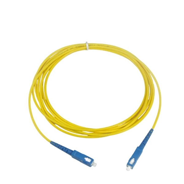
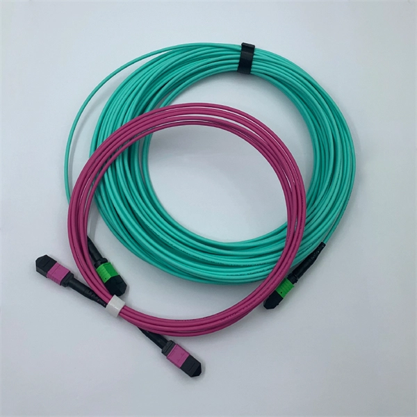
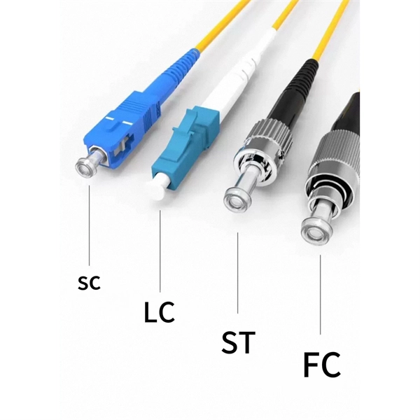
When you look at a fiber optic cable, the outer jacket color instantly tells you what type of fiber is inside. This color-coding system is standardized under TIA-598-C, making it easier for technicians and installers to identify cables at a glance. Understanding fiber‑optic color codes is essential for any technician tasked with installing, maintaining, or troubleshooting modern fiber networks. By adopting the TIA/EIA‑598C standard, you gain a universal “language” of colors that speeds identification, reduces miswiring, and enhances safety. Fiber optic color codes provide the essential identification framework that enables fiber technicians and network professionals to manage complex optical network installations efficiently. This guide explains how standardized fiber strands, cable jackets, connectors, and MPO systems simplify identification, prevent mismatches, and maintain signal integrity. Following industry. This guide explains the latest EIA/TIA-598-D fiber color-coding standard used to identify fiber types, inner fiber sequences, and connector polish styles.
[PDF]