OPGW (Optical Ground Wire) is a kind of cable that comprises the dual functions of grounding and fiber optic communication. It is increasingly utilized in high-voltage transmission lines as a functional element that both safeguards the power system and allows data sharing. OPGW cable in transmission line systems is a unique hybrid solution that combines the functions of grounding and communication into one efficient design. It typically consists of optical fibers encased within an aluminum or steel wire, providing both strength and data transmission capabilities. Enter Optical Power Ground Wire (OPGW) cables 1 —a technology that addresses these needs in a single, integrated solution. As someone who has spent years in the optical communications industry, I've witnessed firsthand how OPGW cables have transformed the landscape of power and telecommunication. An optical ground wire (also known as an OPGW or, in the IEEE standard, an optical fiber composite overhead ground wire) is a type of cable that is used in overhead power lines. An OPGW cable contains a tubular structure with. OPGW is primarily used by the electric utility industry, placed in the secure topmost position of the transmission line where it “shields” the all-important conductors from lightning while providing a telecommunications path for internal as well as third party communications. This guide explores its design, advantages, and applications in modern energy and telecom.
[PDF]
Recommendation ITU-T L. 89 describes the general requirements and a design guide for suspension wires, telecommunication poles and guy-lines that support aerial cables for optical access networks. This Recommendation also describes loads applied to the infrastructures. Aerial infrastructure. Teleworking, online games, online medical consultations, online education - all these services are enabled by fast fi bre optic broadband networks. The intent of such a. These cables vary significantly in material, construction, and application. The core composition and number of wire strands determine their strength, flexibility, durability, and resistance to environmental factors. Understanding the different types helps in selecting the right cable for. 40. FO-VC2 JOINT USE - VERICAL MIDSPAN CLEARANCES 48. FO-GB GROUNDING AND BONDING 49. APPENDIX A - COVER SHEET / TOC 52.
[PDF]
Tray cables (TC) are multi-conductor cables designed and rated for installation in cable trays and raceways or supported by messenger wires. Cable tray may be used as the Equipment Grounding Conductor (EGC) in any installation where qualified persons will service the installed cable tray system. There is no restriction as to where the cable tray system is installed. The metal in cable trays may be used as the EGC as per the limitations. maintain spacing or to keep cables in place when the tray is ect the minimum bend ra-dius for cables as they exit the bottom of the cable tray. A rung spacing of 6 to 9 inches (150 to 230 mm) is preferable when the cable tray cont d for instrumentation and control applications that require. The most frequently used tray cables are: Type TC – Tray Cable – (NEC Article 336) –Power and control tray cable type TC is a factory assembly of two or more insulated conductors, with or without associated bare or covered grounding conductors, under a non-metallic jacket. TC cables are rated for. Hubbell Wiring Device-Kellems and Hubbell Premise Wiring are divisions of Hubbell Incorporated, a U. headquartered manufacturer with over 130 years of supplying solutions for the electrical and data markets. At the panel, the cable is installed in conduit (s) for the vertical.
[PDF]

Discover the key differences between optical fiber cables and copper cables. OPTRAL analyzes the advantages and disadvantages to enhance connectivity. Optical and copper interconnection technologies represent two distinct approaches to data transmission, each with its own advantages and limitations. While fiber optics dominate in performance, copper retains its technical and economic justification. But how do you decide which one is best suited for your needs? This article delves into the technical comparison between copper and fiber optic cables. When it comes to modern data transmission, Fiber Optic cables and Copper Cables play pivotal roles in ensuring seamless connectivity. What Are Fiber Optic Cables? Fiber Optic cables function by transmitting data in the form of light pulses through optically pure glass fibers. These fibers are. “Fiber offers multiple technical advantages, including exceptional bandwidth, low attenuation and distortion over long distances, reduced bulk, as well as isolation from electromagnetic interference (EMI) and electrostatic discharge (ESD). ” Let's explore the characteristics, advantages, and. The two core material technologies used in almost all cables are fiber optic, and copper wiring. Whether you're looking at an HDMI cable, a USB cable, Ethernet patch cable, or any other kind of network of data transmission cabling, they are all built using copper or fiber optic internal wiring.
[PDF]
CRU provides comprehensive, accurate and up-to-date price assessments and research reports for bare optical fibre across various key regional markets, combined with insights into the factors and events affecting markets. Market Forecast By Mode (Single Mode Fiber, Multi-Mode Fiber), By End-Use (Telecommunications, Networking, IT & Data Centers, Broadcast), By Application (Telecommunication, Power Utilities, Medical, Industrial), By Fiber Type (Glass Fiber, Plastic Fiber) And Competitive Landscape How does. Based on our observations and market communication with upstream suppliers, the single-mode fiber market in China has experienced an unprecedented price surge in the first two months of 2026. This article summarizes the latest fiber optic price data as of March 9, 2026, along with the recent. According to APO Research, The global Fiber Optic Cables market was valued at US$ million in 2023 and is anticipated to reach US$ million by 2030, witnessing a CAGR of xx% during the forecast period 2024-2030. North American market for Fiber Optic Cables is estimated to increase from $ million in. How does 6W market outlook report help businesses in making decisions? 6W monitors the market across 60+ countries Globally, publishing an annual market outlook report that analyses trends, key drivers, Size, Volume, Revenue, opportunities, and market segments.
[PDF]
Abstract: Detecting partial discharges in cable joints is critical for timely defect identification and reliable transmission system operation. The electric field distribution of the optical fiber-implanted cable joint was simulated, followed by electrical performance tests, demonstrating that optical fiber implantation had a negligible effect on the electrical properties of the cable joint. A platform utilizing Mach–Zehnder–Sagnac. The results show that the average sensitivity of the sensor in the 10 kHz–80 kHz range is 71. 0 dB higher than that of the piezoelectric transducer, with a maximum signal-to-noise ratio of 65. To improve the long-term reliability and sensitivity of the sensing system, a novel method for cable joint monitoring based on implanting optical fibers. However, there is an industry gap in the literature about the highly sensitive fiber optic-based PD solution based on the acoustic emission principle. This paper aims to fill such an industry gap. In this paper, the fiber optic-based PD sensing (OptiFender) technology is applied to monitor the PD.
[PDF]
Fiber optic "cable" refers to the complete assembly of fibers, other internal parts like buffer tubes, ripcords, stiffeners, strength members all included inside an outer protective covering called the jacket. Cable provides protection for the optical fiber or fibers within it appropriate for the environment in which it is installed. You will also learn how different aspects of the product can affect budget and design. ■ The Five Key Parts of a Fiber Optic Cable A fiber optic cable. A fiber optic cable consists of five basic components: the core, the cladding, the coating, the strengthening fibers, and the cable jacket. When searching for a fiber optic cable, we need to pay attention not only to the connectors, such as SC to ST fiber cable, LC to SC fiber patch cable, or SC to. A TOSLINK optical fiber cable with a clear jacket. These cables are used mainly for digital audio connections between devices. This advanced cabling solution allows fast, secure data transfer and telecom over long distances. Understanding the components within a fiber optic cable enables. While fiber optic cable itself is cheaper than an equivalent length of copper cable, fiber optic cable connectors and the equipment needed to install them have typically been more expensive than their copper counterparts.
[PDF]
In 2024, Top exporters of Optical fibre cables, made up of individually s are China ($2,363,805. 65K, 379,127,000 Kg), United States ($1,645,814. 71K ), Mexico ($1,313,955. 67K, 18,156,300 Kg). 17 billion (according to external trade statistics of 117 countries). There are no trade data (2023) for such exporters as Korea. Asian countries collectively account for nearly 50% of global exports, with China dominating in both sectors. Looking at both optical fiber and optical cable, China ranks first with an export share of 29. 6%, followed by the United States (12%) and Mexico (11%), which shows that technology is highly. Volza's Big Data technology analyzes over 3. 5 billion verified shipment records across 203 countries to help exporters and importers identify new Fiber Optical Cable buyers and suppliers, discover profitable markets, and connect with reliable trade partners worldwide. According to Volza's Global. Analyze Fiber Optical Cable export import data and locate key markets, reliable suppliers, and active buyers by utilizing Eximpedia's data-centric platform. Whether you're a supplier looking for high-demand markets or a buyer sourcing Fiber Optical Cable from reliable exporters, Eximpedia's. Find verified buyers and sellers of fiber optic cables in 180+ countries along with their valid phone numbers and email ids. The top 3 Buyer countries for fiber optic cables are “ CHINA ”, “ UKRAINE ”, “ UNITED STATES OF AMERICA ”,.
[PDF]
Since fiber-optic cables use light to transfer data instead of electricity they actually generate less heat than traditional cables! This absence of heat makes them less likely to catch fire and less of a fire hazard than normal metal wires. A rigorous analysis of optical power density, thermal ignition mechanisms, and the role of Automatic Laser Shutdown in preventing fire hazards in EDFA-amplified fiber networks. Article Inspiration This article was inspired by the Fiber Optic Association (FOA) March 2026 Newsletter — Seen On The. Myth #1 – Fiber-optic cables are a fire hazard. The general assumption is simple: once installed, the cable does its job – transmitting data from point A to B – and that's it. Understanding the safety hazards that go with fiber optic cable is critical for those who install or maintain fiber optic systems. As electrical professionals, most of us take fiber optic (FO) safety for granted. Since fiber optic cable carries no electricity, we don't worry about electrocution. This means they won't produce sparks or arcs that could ignite a flammable atmosphere. In a Class I Division 1 or Zone 1. Fiber-optic cables are the backbone of modern connectivity—powering 5G networks, global internet backbones, and data center interconnections with near-light-speed data transmission. While these cables are engineered for durability (with some rated to last 25+ years), they are not invulnerable.
[PDF]
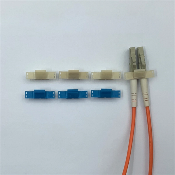
The other side of the pigtail is open and is connected to a fiber optic cable. This creates a stable and reliable connection between network equipment. They are the bridge between fiber optic cables in the field and the equipment or patch panels that manage them. By combining factory-installed connectors with spliced bare fiber, pigtails ensure that network installers can create fast, reliable, and cost-effective terminations. DINTEK supplies this equipment, but the pigtails can also be. In the intricate ecosystem of fiber optic networks, two components play a critical role in ensuring seamless connectivity: patch cords and pigtails. A fiber optic pigtail is a type of fiber optic cable with only one end that has a factory-terminated connector and the other end exposed as bare fiber. When compared to field-installed rapid. Today, I'll show you how to pick the right patch cord or pigtail — step by step. You plug it into a switch, router, or patch panel. It's ready to use out of the box. A pigtail is for splicing.
[PDF]
A shortage of fiber-optic cable equipment is blamed on AI data center demands as well as US protectionism. Warnings about a US fiber crunch that could slow down broadband deployment have intensified since the summer. Very recently, Mitch Landrieu, senior advisor to president and White House infrastructure coordinator made a statement that says, “Just like president Franklin Delano Roosevelt's Rural Electrification Act made a historic investment in rural areas bringing electricity to nearly every home in. According to 2022 data from the United States International Trade Commission, U. manufacturing capacity met only about 53% of the country's demand for optical fiber, the core component of fiber optic cable. currently relies heavily on imports to meet the increasing demand. That's a problem, considering fiber optics are the backbone of modern communications, powering everything from global internet. From a splicer's standpoint, ribbon cable is “much more user friendly and much more organized” because multiple fibers are bonded together. In August, Incab America, a Texan maker of fiber-optic cable, notified customers. However, a significant paradox exists: despite its immense benefits, fiber optic infrastructure is not universally available. This article aims to dissect the multifaceted reasons behind this uneven distribution, providing a comprehensive overview of the challenges and potential solutions for.
[PDF]
The modern world relies heavily on electrical and communication cables that must be managed and supported across vast distances in commercial and industrial settings. A cable tray is an organized support structure designed to secure and route these insulated electrical cables. In the electrical wiring of buildings, a cable tray system is used to support insulated electrical cables used for power distribution, control, and communication. Cable trays are used as an alternative to open wiring or electrical conduit systems, and are commonly used for cable management in. Whether you're planning a new office setup or upgrading your existing network, the choice of a cable tray system plays a significant role in ensuring the reliability and scalability of your structured cabling solution. It acts as a. en completely installed, without damage either to conductors or structural system use maintain spacing or to keep cables in place when the tray is ect the minimum bend ra-dius for cables as they exit the bottom of the cable tray. A rung spacing of 6 to 9 inches (150 to 230 mm) is preferable when. Explore various cable tray types and sizes for electrical installations. Learn about ladder, perforated, solid-bottom, wire mesh, and channel trays in this complete guide. What is Cable Tray Systems? 1.
[PDF]
Understand how to choose fiber optic cable by comparing single‑mode vs. multimode, network speed and distance needs, cable jackets/fire ratings, connectors, cost and future‑proofing for data and telecom networks. Written by Ben Hamlitsch, trueCABLE Technical and Product Innovation Manager RCDD, FOI There are many advantages when it comes to using fiber optic cable in your telecommunications infrastructure. Fiber optic technology offers several key benefits including higher bandwidth for data. Fiber optic internet is a form of broadband that uses a network of bundled tiny glass fibers called fiber optic cables to deliver internet service via light waves. internet service? The technical difference is that most forms of traditional internet service transfer information by sending electric. Transmitted with flashes of light through strands of glass, fiber-optic internet is the most advanced broadband technology available. Because data can travel faster across greater distances with glass than with cable, the connection speed is much faster with a 100% fiber-optic network.
[PDF]
Drawing on IEC standards and industry research data, it outlines the coverage of mainstream outdoor fiber optic cable types, selection criteria, and best practices for installation, providing a systematic reference for outdoor fiber optic cable deployment. This document serves as a guide for outdoor fiber optic cable selection and installation for professionals in the telecommunications industry. Fiber optic cables for outdoor applications are engineered to withstand the more demanding conditions seen outside, from environmental extremes to mechanical forces. These are the outdoor fiber optic cables you see strung along telephone poles (aerial), installed inside an underground duct, or even. Outdoor fiber optic cables transport data and communications signals over long distances while enduring extreme environments. Whether you're linking buildings, running broadband in rural areas, or building 5G infrastructure, the right cable matters. It affects performance, maintenance, cost, and reliability. Our team will make sure the configuration is tailored to your needs and will provide a detailed quote. Email us using the Request a Quote below, or. hing, conduit and temp rature variations. The Outside Plant cable. These cables are thoroughly tested designed for installation in pathways that are subjected to wide product line offers 6 and 12 fibers per and verified to Telcordia GR 20 a loose tube cables and hybrid design o ts to specific.
[PDF]
Optical Fiber Cables Price in Bolivia - 2025 - Charts and Tables - IndexBox. What's the difference? Get instant access to more than 2 million reports, dashboards, and datasets on the IndexBox Platform. The average optical fiber cables import price stood at $3,850 per ton in 2023, reducing by -8. 1%. Buyers typically pay for fiber optic cable by length, fiber type, and installation complexity. Main cost drivers include cable grade (indoor vs outdoor, armoured), distance, and labor for trenching, splicing, and termination. This guide presents ranges in USD and practical price estimates to help.
[PDF]