The fastest way to test a fluorescent tube is with a multimeter set to continuity mode. Each end of the tube has two pins connected by a thin filament inside the glass. If either filament is broken, the tube is dead. The whole test takes about 30 seconds per tube once you know what. Knowing how to use a multimeter to check an LED tube light is a valuable skill for homeowners, electricians, and anyone involved in maintaining lighting systems. Perhaps it's a simple wiring problem, a. One essential tool for diagnosing LED tube light issues is a multimeter. This process measures electrical resistance to determine if the tube has suffered an internal failure before replacing the bulb or investigating the ballast. If you don't have a multimeter to use, a simple coin cell battery holder with leads will let you know. Yes, you absolutely can test an LED light with a multimeter! It's a straightforward process that helps you figure out if your LED is working or if it's the source of a problem in your circuit.
[PDF]
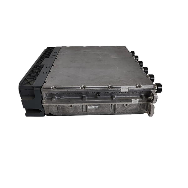
Mouser offers inventory, pricing, & datasheets for Copper Heat Sinks. Check each product page for other buying options. Need help? Copper heatsinks provide efficient heat transfer to keep your electronic components running at optimal temperatures. Discover the perfect cooling solution. Heat sinks are thermal management components designed to dissipate heat from high-power electronic devices and prevent overheating. Their core function is based on the principles of conduction, and convection, transferring heat from a heat source—such as a CPU, power transistor, or BGA package—to. Heat Sinks Cup Clips for TO-5 Case Style Semiconductors, 14. Heat Sinks Cup Clips for TO-5 Case Style Semiconductors, 14. A tariff of 10% may be applied if shipping to the United States. Due to copper's superior thermal conductivity (approximately 400 W/mK, nearly twice that of aluminum), copper heatsinks. Lot Of 2 Dell Copper Aluminum Heat Sink. Pulled From Clean Unit Sold As Scrap 100 PCS (8 Different Sizes) Heatsink Kit with Conductive Adhesive Tape, Alumi. Copper Aluminum Heat Sink Lot Sold As Scrap.
[PDF]
You can test a photocoupler with a multimeter. This checks if its output changes when you power its input. This gives you the most accurate test results. This detailed guide will walk you through the process of testing an optocoupler using a multimeter, covering various scenarios and providing practical advice to ensure accurate results and avoid common pitfalls. We'll explore the underlying principles, delve into different testing methods, and. In this episode #0018 of Electronic Components Testing, we reveal how to test an optocoupler (optoisolator) using a digital multimeter step by step. This simple yet powerful technique will help you detect faulty optocouplers on circuit boards without desoldering them. Always. What are the methods to test optocoupler? The quality of the optocoupler can be determined by measuring the forward and reverse resistance of its internal diode and triode. Jotrin Electronics Limited will tell you that the reliable detection methods,as follows: 1. From basic circuit design to complex industrial systems, accurate optocoupler. Optocoupler is one type of ICs, It isolates input and output section by using optical technology this feature increase safety of circuit. Optocoupler has many part number, different part number has different output type so before checking it has to use part number to research with datasheet and.
[PDF]
Using a multimeter, check continuity between the black connector and the marked pin of the optocoupler input that is not working. If there is no continuity, the possible causes are: Connect a 5 V to 24 V signal to the input being tested. Measure the voltage at the marked. Using a multimeter, you can perform several tests to assess the functionality of an optocoupler. Each test targets a specific aspect of the optocoupler's operation. An optocoupler is an essential electronic component that transfers signals without a direct electrical connection. more n this video, you will learn how to test an optocoupler (optoisolator) using a. Optocoupler is one type of ICs, It isolates input and output section by using optical technology this feature increase safety of circuit. Optocoupler has many part number, different part number has different output type so before checking it has to use part number to research with datasheet and. If any optically isolated input on the controller is not working, follow the steps below to identify the cause. For our demo purposes, we will be using the PC817, a commonly used transistor output optocoupler in electronics. An opto-isolator contains a source (emitter) of light, almost always a near infrared light-emitting diode (LED), that converts electrical input signal into light, a closed optical channel (also called dielectrical channel, and a photo sensor, which detects incoming light and either generates.
[PDF]
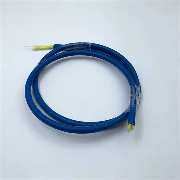
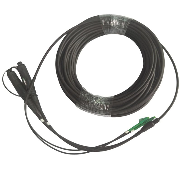
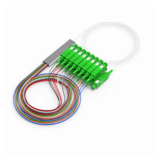
An OTDR is a powerful tool that helps technicians and engineers assess the health of fiber optic cables. OTDRs inject high-powered light pulses into the fiber using specialized laser diodes. As these light pul.
[PDF]
In this article, you will learn the step-by-step process of testing your solar panels using a multimeter. We will cover the essential tools you need, the specific measurements to take, and how to interpret the results. By the end of this guide, you will be equipped with the knowledge to diagnose. Solar panels are usually tested under standard conditions using a light source that mimics the light from the sun on a clear day. You can use the following method if you want to test your solar panel under standard conditions. Testing solar panels is easy with a multimeter! To test the current. Your multimeter is your best friend when testing solar panels. You can use it to check: Here's how: Multimeter — I recommend getting one that is auto-ranging. Also, a simple voltmeter won't work here. You need a multimeter that can measure both volts and amps. Locate the open circuit voltage. Learning to test a solar panel with a multimeter is an investment in your knowledge and ability to manage your own solar energy system or provide valuable services in the growing solar industry. Measure Voc (open circuit voltage) — if it reads 0V, the panel or wiring is dead. If it reads 60–80 % of rated, a bypass diode has failed. Perfect for DIY solar builders, RV owners, o. more Audio tracks for some languages.
[PDF]