Use the enterprise network product hardware query tool ( com/onlinetoolsweb/lpcmmt/en/index. html) to check optical module models supported by the interface based on the switch model. The optical module cannot be properly identified and optical module information cannot be obtained. The working rate, duplex mode, and. This article helps network operators and field technicians compare compatible module options, validate switch requirements, and troubleshoot failures fast—so you can restore service without guesswork. Which option should you choose? How can I tell whether a Huawei CloudEngine transceiver is truly. Describes what an optical module is and FAQs, including the fundamentals, appearance and structure, key performance counters, common types, and naming conventions of optical modules, causes of optical module failures and corresponding protection measures, types of optical modules supported by. This article summarizes several solutions for using optical modules with switches and common problems encountered during usage, along with specific solutions. Huawei S5720-32P-EI-AC Switch II. How to Configure Optical Ports on Huawei S5720-32P-EI-AC Switch? Problem: All optical ports cannot be. Optical Module quality control-Test Procedure In order to ensure that the optical module we deliver do not have compatibility problems. Reason: Optical modules from various vendors differ in.
[PDF]
These modules typically consist of a laser or LED transmitter, a photodiode receiver, and supporting electronics. Optical modules are compact devices that convert electrical signals into optical signals and vice versa. They are used in fiber optic communication systems to transmit data over long distances with minimal loss and interference. The Cisco NCS 2000 Series encompasses platforms from Cisco NCS 2002 onwards. In intelligent computing centers built around large-scale GPU clusters, network bandwidth, latency, and reliability directly determine the efficiency of AI training, big data processing, and other tasks. As a core component connecting servers, switches, and storage systems, optical modules play a. What is an SFP? SFP (Small Form-factor Pluggable) is a compact, hot-pluggable network interface module used to connect network devices (switches, routers, firewalls) to fiber optic or copper cables. The OLT is installed at the headend and each OLT port connected into the fiber to the designated service area and the splitters installed to serve the intended users. Operating at the physical layer of the OSI model, optical modules are core devices in optical.
[PDF]
The optical budget refers to the maximum allowable signal loss between the transmitter and receiver in a fiber-optic link. It ensures that the received signal is strong enough for the equipment to process data without errors. Calculated in decibels (dB), it is the difference between the. After measuring the loss of a fiber link, you now have to determine if that fiber link loss is acceptable or not. You can either compare this loss value to the application requirement or calculate the expected loss based on how many connectors and splices are in the link along with the length of. Optical module channel loss resistance refers to the maximum optical path attenuation that an optical transceiver module can tolerate while still maintaining compliant signal integrity, error performance, and link stability. There are many reasons for optical fiber loss, such as optical fiber material's absorption/scattering of light energy, bending.
[PDF]
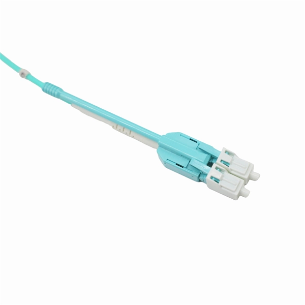
This guide provides a fully updated and industry-ready overview of LC fiber optics, explaining the origin and design of LC connectors, their key features, and the complete ecosystem of LC-based products used in modern networking. LC fiber connectors, as the most well-known representative of SFF (Small Form Factor) connector, are widely adopted in today's LAN and data center cabling. You may find LC connector has a strong family which includes but not limited to LC optical fiber connectors, LC fiber patch cables, LC fiber. Data centers will keep dominating optical module demand as AI and cloud drive revenue growth through 2030. Optical module demand is being pulled in two directions at once, faster bandwidth for dense networks and tighter constraints on power, security, and lead times. With global R&D projected to. LightCounting has proudly served our industry for 22 years with reports and services designed to help executives plan and run their businesses. We support decision-making based on our data, expert analysis and trusted forecasts. It covers LC connectors, LC patch cables, uniboot designs, armored. Optical Module Package Market was valued at 8942 million in 2024 and is projected to reach US$ 20220 million by 2032, at a CAGR of 12. With the surge in data traffic and the increasing demand for higher bandwidth, 100G optical modules have gained immense traction. These modules facilitate high-speed.
[PDF]
This step-by-step guide aims to provide a comprehensive understanding of the techniques and considerations involved in successfully connecting optical fibers, offering invaluable insights for professionals and enthusiasts in the field. In high-speed data networks, the seamless integration of fiber optic cables with SFP (Small Form-Factor Pluggable) modules is critical for reliable signal transmission. SFP transceivers bridge electrical and optical signals, making them indispensable in data centers, telecom networks, and. Proper connection of fiber optic cables is essential to harness these benefits fully, as even minor errors can lead to significant performance issues like signal loss. This article will guide you through the necessary tools, materials, and methods on how to connect fiber optic cables effectively. This section describes how to install optical transceivers on the SFP or SFP+ ports and connect them to the ports of the peer device using optical fibers according to the network plan. The USG supports both 1 Gbit/s, 10 Gbit/s, and 40 Gbit/s optical modules. The optical modules at both ends are. There are many types of fiber optic connectors, including SC, LC, FC, ST, D4, MU, MT/MPO, etc. These connectors can be divided into single-mode and multi-mode fiber optic connectors according to their structure and purpose. In this tutorial.
[PDF]
In the field of optical communication, the packaging of optical devices plays a crucial role in the performance and application of optical modules. Common optical device packaging methods include COB (chip-on-board packaging), BOX and coaxial packaging. Today, we will discuss the differences. This article analyzes the requirements of optical transceivers and discusses packaging methods and optical chip types to help readers better understand their design and manufacturing process. They are used in telecom and data communication applications and can be packaged in different ways, including TO, Box, and COB packaging. Regardless of the type of optical module, the. COB packaging means chip-on-board packaging, and the laser chip is adhered to the PCB substrate, which can achieve miniaturization, light weight, high reliability and low cost. The traditional single-channel 10Gb / s or 25Gb / s rate optical module uses SFP package to solder the electrical chip and. The optical transceiver module has three major components, which are opto-electronic devices (TOSA/ROSA), a circuit board with electronic components (PCBA) and optical interfaces (housings) such as LC, SC and MPO. Figure1: Components of an Optical Transceiver The optical transmitting part is.
[PDF]
It supports multi-mode fiber with a reach of 300m via a duplex LC connector. Designed for extended temperatures (-40°C to 85°C), it includes Digital Optical Monitoring (DOM) and guarantees full compatibility with H3C equipment, making it ideal for harsh environment deployments. Optical modules transmit signals over optical fibers. Optical transmission features low loss and is fit for long distance transmission. The. Max. Note: Due to DigiKey value-add services the packaging type may change when product is purchased at quantities beneath the standard package. Buy now, ships today. SFP-XG-SX-MM850-D-C - Transceiver Module Networking and Communications 10Gbps 850nm LC Duplex Pluggable, SFP+ from ATGBICS. View. This H3C® SFP-XG-SX-MM850-A compatible SFP+ transceiver provides 10GBase-SR throughput up to 300m over multi-mode fiber (MMF) using a wavelength of 850nm via an LC connector. Our transceiver is built to meet or exceed OEM specifications and is guaranteed to be 100% compatible with H3C®. With a data rate of 10. This transceiver is compliant with SFF-8431, SFF-8432 and IEEE 802. 3ae standards and for seamless interoperability in multivendor environments.
[PDF]
This guide breaks down practical differences—core geometry, wavelengths, connector types, performance limits, cost trade-offs, and ideal use-cases—so you can pick the right optical modules with confidence. SFP (Small Form-factor Pluggable) is a compact, hot-swappable module used in network devices such as switches, routers, and servers to provide network connectivity and is widely used in network communications. By using different interfaces and single-mode or multimode fiber depending on the. Multimode and Singlemode optical modules differ in terms of fiber type, transmission distance, cost, and application scenarios. Understanding these differences is the first step in selecting the right module. Multimode Optical Modules: These modules are typically used for shorter transmission. Multimode SFP module offers a practical solution for short- to medium-range 100G transmissions, particularly in high-density environments where performance, compatibility, and cost control are equally critical. At the end of the day, they answer one simple question: How much bandwidth can this fiber handle, and how far can it go? “OM” stands for Optical Multimode, which is a classification system for multimode fiber.
[PDF]
Optical modules typically have an electrical interface on the side that connects to the inside of the system and an optical interface on the side that connects to the outside world through a fiber optic cable. An optical module is a typically hot-pluggable optical transceiver used in high-bandwidth data communications applications. Composition of Optical Modules The optical module, known as Optical Transceiver in. The optical module serves as a crucial component in optical fiber communication systems, operating at the physical layer, which is the lowest layer in the OSI model. Its primary function is to achieve optoelectronic conversion by converting electrical signals into optical signals and vice versa. Operating at the physical layer of the OSI model, optical modules are core devices in optical.
[PDF]
At the heart of every optical transceiver lie three essential components, often called the “Three Pillars” of optical communication: Laser — generates light. Modulator — encodes data onto the light. Photodiode — decodes light signals back into electrical form. As an essential component of optical fiber communication, optical modules are optoelectronic devices that facilitate the conversion between optical and electrical signals during the transmission process. Operating at the physical layer of the OSI model, optical modules are core devices in optical. An optical module usually consists of an optical transmitting device (TOSA, including a laser), an optical receiving device (ROSA, including a photodetector), functional circuits,main control circuit board (PCBA), housing and optical (electrical) interface and other components. Together, lasers, modulators, and. That is, metal medium communication represented by coaxial cables and network cables is gradually being replaced by optical fiber media. Composition of Optical Modules The optical module, known as Optical Transceiver in. This comprehensive guide breaks down the internal structure, core components (TOSA, ROSA, lasers), and operational mechanisms of SFP optical modules, enriched with technical insights and real-world applications. These modules typically consist of a transmitter, which converts electrical signals into a light signal, and a receiver, which converts the received signal back.
[PDF]
An optical module is a typically hot-pluggable optical transceiver used in high-bandwidth data communications applications. Optical modules typically have an electrical interface on the side that connects to the inside of the system and an optical interface on the side that connects to the outside world through a fiber optic cable. The form factor and electrical interface are often specified by an int. Electrical Interface TypesThere have been multiple variants of the electrical interface of optical modules that have been used over the years. The earliest forms of optical modules had an analog electrical interface. In the transmit dir. Many different forms of optical modulation and multiplexing have been employed in optical modules. The most common modulation technique historically has been or NRZ. Optical modules have a series of components inside, some of which have received attention from standards development organizations. In many cases, the baud rate of the optical interface do.
[PDF]
The set interface optics-monitor enable command enables or disables optical module monitoring and alerting for all switch interfaces. You can check monitoring information of optical modules in the run show interface diagnostics optics command result and in the log file. This chapter describes how to configure the Optical Amplifier Module and Protection Switching Module (PSM). When you plan to replace a configured optical module with a different type of optical module, you must clear the configurations of the old module before you install the new module. For. Specifies the management interface, core and advance management features, and memory map. It is supported by a set of supplements (IA's) for specific applications. Coherent-CMIS: Provides extensions to CMIS to manage modules with coherent interfaces. CMIS-Form Factor: Provides details of HW pins. When the optical module on an interface is faulty, you can run the display commands to view information about the optical module. Related Information Video Identify a Huawei-Certified Optical Module Run the display transceiver [ interface interface-type interface-number | slot slot-id ] [ verbose ]. By default, Cisco switches perform authenticity validation on inserted optical modules. If a module is identified as non-Cisco original, the switch may shut down the port, trigger an alarm, or display a warning message. For information about which F5 ® transceiver modules support DDM, see F5® Platforms: Accessories.
[PDF]
Optical trap or "tweezers" is a device used to apply piconewton sized forces and make precise measurements on a scale of roughly one micron. It can be created by applying a precisely focused laser onto a dielectric material. Thorlabs' OTKB (/M) Modular Optical Tweezers provide users with a tool for trapping and manipulating microscopic-sized objects. These laser-based tweezers, or traps, have been employed in numerous biological experiments. Biological applications for optical tweezers include trapping viruses and. Our advanced optical trap generator based on ultra-fast AOD technology. Versatile and flexible optical trap manipulation designed for biological samples. Learn to calibrate the 20. Use calibration information to observe the rotation of E. coli bacteria, and determine the forces required to stop this rotation. Based on their design, Thorlabs has collaborated with the aforementioned authors to design an OTKB optical trapping kit that includes all necessary components and provides the same capabilities. Enclosed into a high-quality aluminum box and assembled onto the. Torr Scientific offers a range of magneto-optical traps (MOT) (also known as atom trap chambers) used as part of ultra-cold vacuum systems, to capture atoms for testing purposes. This is a chamber module, formed of low-magnetic permeability materials for use at ultra-low temperatures nearing.
[PDF]
Amphenol AOP 100Gbps QEPT® High-Speed 4-TRX Optical Module - Quad Embedded Pluggable Transceiver - rugged, it is designed for extended temperatures and highly challenging applications where both reliability and performance are critical. The LEAP® On-Board Transceiver is a commercial 12-channel duplex optical. Amphenol's 300Gb/s Leap ® High-Speed Optical Module is faster, smaller, and more cost and power efficient than most conventional datacenter interconnects. Supports non-standard protocols in this range of datarates. Note CDR operational bit rate of 25-25. 05Gbps per channel, or 300Gbps in total when considering all channels. Engineered to excel in harsh environments, they are the go-to choice for high-speed, mission-critical applications.
[PDF]

In this episode, we will demonstrate the correct and incorrect procedures side by side to show you how to properly replace optical modules and prevent any abnormalities in their usage. When you plan to replace a configured optical module with a different type of optical module, you must clear the configurations of the old module before you install the new module. For. An optical module is an optoelectronic conversion device that transmits data by converting electrical signals into optical signals. Common types of optical modules include SFP, SFP+, SFP28, QSFP, QSFP28, etc. Different types of optical modules have different performance parameters such as speed. Small Form-factor Pluggable modules (SFP module) are the workhorses of modern network connectivity, enabling flexible fiber optic or copper links between switches, routers, firewalls, and servers. Whether you're upgrading bandwidth, replacing a faulty unit, or reconfiguring your topology, knowing. Optical modules are hot swappable, and you do not need to power off the device when replacing optical modules. Optical modules are electrostatic-sensitive components. Therefore, you must take ESD protection measures when replacing optical modules.
[PDF]