An analog accessory for use in a system for testing protection relays is provided, comprising inputs connectable to the current outputs of a test-set for protection relays and voltage outputs connectable to a protection relay to be tested. The register contains national patents and information related to European Patents validated in Malta. It currently provides European patent numbers, filing dates, titles, abstracts, classifications, applicants, bibliographic data, status, priorities, expirations, annuity/renewal fees. The utility model discloses a power plant relay protection tester, belonging to the technical field of relay protection testers, which comprises a relay protection tester body and a shell for placing the relay protection tester body, wherein a partition plate is arranged in the shell, a driving. Application to amend a patent application or registration. Convert a European patent application to a National patent. Request an extension of a time limit for the submission of patent documents. By providing an electric circuit adapted to convert current. Background Relays and metering are an important part of power generation, power transmission, and power con- sumption in electric power systems and the power grid. Relays provide monitoring and protection of equipment and personnel.
[PDF]
If a fault is detected, the relay will send signals to adjacent relays and circuit breakers, allowing the closest breaker to trip first while other breakers delay their operation. This selective coordination helps isolate the faulted zone while maintaining the power supply to the. A protection relay is a crucial component of electrical systems that safeguard infrastructure, employees, and equipment from electric problems and malfunctions. It functions as a watchdog by constantly surveying multiple system components including voltage, current, frequency, and phase angle. It. A protective relay is the vigilant guardian of electrical networks, constantly monitoring and analyzing electrical parameters to detect abnormal events. Acting as the first line of defence, it swiftly detects faults, such as short circuits or overcurrents. It triggers protective actions to isolate. In electrical engineering, a protective relay is a relay device designed to trip a circuit breaker when a fault is detected. : 4 The first protective relays were electromagnetic devices, relying on coils operating on moving parts to provide detection of abnormal operating conditions such as. A protective relay is an intelligent device that senses abnormal electrical conditions, such as overcurrent, under-voltage, or frequency deviations. It initiates the operation of circuit breakers to isolate the affected section.
[PDF]
The total interruption time for a modern high-voltage SF6 circuit breaker is typically between 40 to 60 milliseconds on a 50Hz grid, or 2 to 3 cycles. This is the total time from the trip signal to the final arc extinction, a critical parameter for grid safety. While knowing the total time is a. When a SF6 circuit breaker (CB) hits its critical low pressure, its fault interrupting capability can be compromised. Most TOs protect against this by either auto-opening the CB prior to reaching the critical low-pressure level or by blocking the CB from tripping (when it reaches the critical. The protected zone is defined and limited by different things depending on the protection function. Definite time delay means that the protection operate time dose not change or depend on the fault type or the fault current magnitude. Instead of oil, air, or a vacuum, a sulfur hexafluoride circuit breaker uses sulfur hexafluoride (SF 6) gas to cool and quench the. Page 1 Content Instruction Manual circuit- breaker GL317 With spring operating mechanisms FK3- 4 Administrator First issue Compiled by Approved by 19- 11- 2012 J. Texier Imagination at work Grid Solutions 04- 2017 D1736EN/03 GE Information 1/10. Page 2 Content Instruction Manual This. A comparison of the time it takes protective devices to operate when certain levels of normal or abnormal current pass through them. LV circuit breaker ratings.
[PDF]
The standard industry practice is to set overload relays at 125% of the motor's nameplate Full Load Ampere (FLA) rating. Plug Setting Multiplier (PSM) indicates how many times the determined relay secondary current (typically the CT secondary) exceeds the relay pickup (plug) current. It is the key quantity utilized in IDMT (inverse definite minimum time) curves to calculate the basic operating time. PSM (Plug Setting. An overload relay is a crucial device for motor control, designed to prevent motors from overheating or suffering winding damage due to excessive current. Motor overload relays protect against sustained overcurrent conditions that cause dangerous overheating, insulation breakdown, and premature. Overload relays protect motors and equipment from thermal damage caused by prolonged overcurrent conditions. IEC 60255 defines standards, formulas, and performance requirements, enabling accurate calculations and real-world applications. How is the overload relay current calculated? Why include. Setting motor overload relays correctly is critical for protecting AC induction motors from sustained overcurrent conditions while avoiding nuisance trips during normal starting transients. This occurred when the relay F was set at 1. The complaint was that the relay tripped instantly on overload when the thermal damage curve show plotted for a specific current that was less t an.
[PDF]
The SEL-221F Relay uses positive-sequence memory voltage polarized mho distance elements for phase and ground distance protection. These elements expand in proportion to the source impedance to provide more resistive fault coverage than self-polarized mho elements. VAMP 221 arc protection system components. Central unit VAMP 221. I/O units VAM 12L / VAM 12 LD, VAM 10L / VAM 10LD, VAM 3L / VAM 3LX and VAM 4C / VAM 4CRL / VAM 4CD 10 1. Arc sensors VA 1 DA, VA 1 EH, ARC SLx. Schneider Electric VAMP range is an arc flash detection and protection pioneer offering fast and reliable devices to improve safety. VAMP 221 significantly reduces the risk of potential personal damage, and material and production losses caused by arc fault. VAMP 221 complies with the latest standards concerning the. Serial communications ports allow local or remote interaction with the relay. 5” high chassis sizes. The report will identify methodology behind these practices, present issues raised by the integration of microprocessor relays and the internal logic and external communication configurations, ying. In the design of electrical power systems, the ANSI Standard Device Numbers denote what features a protective device supports (such as a relay or circuit breaker).
[PDF]

Find and discover Relay buyers & importers for all products in Benin, featuring details on their shipment activities, trade volumes, trading partners, and more. View all relay suppliers based on products in Benin. How does 6Wresearch market report help businesses in making strategic decisions? 6Wresearch actively monitors the Benin Protective Relays Market and publishes its comprehensive annual report, highlighting emerging trends, growth drivers, revenue analysis, and forecast outlook. Our insights help. There are 72 Manufacturers in Benin as of April 1, 2026; which is an 9. 09% increase from 2023. The top three states with the most Manufacturers are Atlantique Department with 20 Manufacturers, Borgou Department with 14 Manufacturers, Littoral Department with 11 Manufacturers. Subscribe to global trade data intelligence to discover new business opportunities. Top 10 Companies in Benin: A Profile of Industry Leaders Benin, a coastal nation in West Africa, has witnessed significant economic growth in recent years. The country's business landscape is dominated by a diverse range of companies, spanning various industries and contributing to its overall. It is bordered by Togo to the west, Nigeria to the east, and Burkina Faso and Niger to the north. A majority of the population live on its small southern coastline on the Bight of Benin, part of the Gulf of Guinea in the northernmost tropical portion of the Atlantic Ocean. This report offers comprehensive.
[PDF]

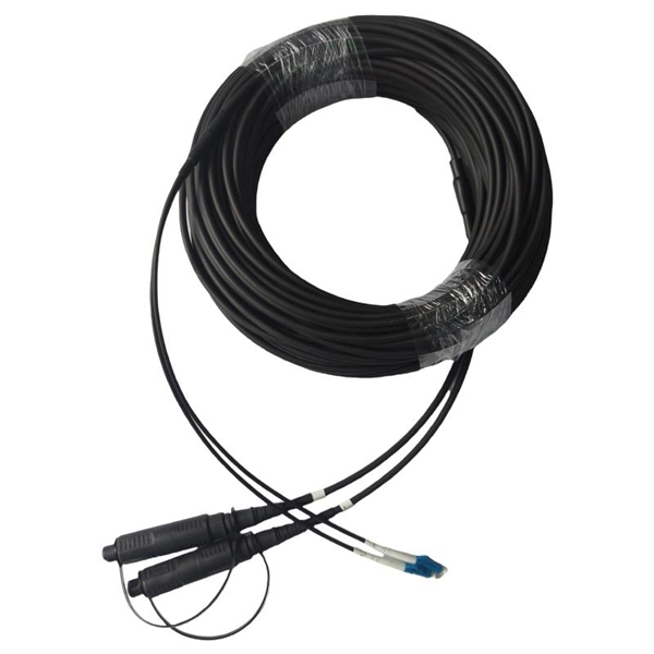
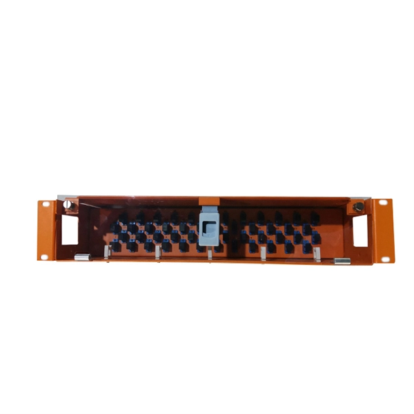
Thinner cables can be utilized to connect the control switch to the relay; this saves space, weight, and cost. The same voltage and current ratings as other types of switches, such as mechanical switches, do not limit relays. This handbook covers the code of practice in protection circuitry including standard lead and device numbers, mode of connections at terminal strips, colour codes in multicore cables, dos and donts in execution. Also principles of various protective relays and schemes including special protection. A control relay is an electrically operated switch that enables current to flow through a coil that closes or opens the switch. Relays use a small current to control a larger current, making them ideal for controlling high-power devices such as motors, lights, valves, and sensors. When a relay contact is open, this will switch power ON for a circuit when the coil is activated. You'll connect a low-power control circuit to the relay's coil (terminals 85 and 86), which then flips a switch for a separate, high-power circuit running through the. Electrical protection relay has two type protecton as HT panel protection and LT panel protection. HT panel protection relay. The HT power supply is received from GO switch and distributed to the. The rectangular devices are test connection blocks, used for testing and isolation of instrument transformer circuits. : 4 The first protective relays were electromagnetic.
[PDF]
Protection: CVTs supply voltage signals to protective relays, enabling them to detect faults and initiate appropriate actions, such as circuit breaker tripping. Control: CVTs can also be used in control systems to monitor voltage levels and provide feedback for voltage regulation. Capacitive Voltage Transformers (CVTs) are common in high-vo tage transmission line applications. These same applications require fast, yet secure protection. However, as the requirement for faster protective relays grows T models whose purpose is to identify which major CVT components contribute. ve Voltage (CVT) and Capacitance Coupled Voltage Transformers (CCVT). With this comprehensive range of accurate power sensing devices coupled with GE's vertical integration approach and skilled design engineering staf, we work closely with our globa ems for applications ranging from high-voltage to. Capacitive Voltage Transformers (CVTs), also known as capacitor voltage transformers, are essential components in high-voltage power systems. They provide a cost-effective and reliable means of measuring voltage and supplying power to protective relays and metering equipment. This essay will delve. Potential transformers and coupling capacitor voltage transformers (CCVT's) have been used successfully for providing voltage to the inputs of meters and relays since the 1960's. It utilizes a capacitive voltage divider in conjunction with an electromagnetic voltage converter to provide a.
[PDF]

This document provides a comprehensive technical overview of the Ring Main Unit (RMU), serving as a reference for power system design, selection, and maintenance. Ring Main Units (RMU s) and Medium Voltage (MV) Switchgear are crucial in MV power distribution. Globally, they each hold about half the market share. MV switchgear handles primary distribution for large industrial facilities and grid infrastructure. RMUs, however, shine in secondary distribution. RMUs are commonly used in secondary distribution systems, particularly in urban areas, industrial complexes, and commercial. Scope of Application: The Ring Main Unit (RMU) is a compact switchgear device used in medium-voltage power distribution systems (typically 10kV–35kV). Some of the key features of the RMU includes SF6 gas insulation, compact and modular construction, integral protection system, fully extendable options. SFA-RM units are designed for supplying reliable energy, protecting electrical equipment in secondary distribution networks up to 17. Their compact design makes them suitable for various network applications such. Loading. Company Introduction:The New Concept Electric Inc. (NCE) was founded in October 2001, with a registered capital of 57 million Yuan. The company now covers an area of 77, 601 square meters (116 acres), and has a building area of 80, 451 square meters.
[PDF]
A relay protection tester is a core device used to verify the performance of relay protection devices. Its working principle can be summarized as “signal excitation – behavior detection. ”. Circuit principle of relay protection tester 1, input AC220V power output control relay K1 is approved by the insurance into the dual voltage regulator for T1 input carbon brush, through large knob to adjust the power into the isolation transformer T1 T2 (part-time riser), heat flow device points. When the transformer wiring type is Y/Y (Y0), the test wiring is very simple: when testing phase A, the tester IA is connected to the phase A of the high voltage side, and the tester IB is connected to the phase a of the low voltage side. ” The tester has a built-in high-precision programmable power supply, capable of simulating various operating. This handbook covers the code of practice in protection circuitry including standard lead and device numbers, mode of connections at terminal strips, colour codes in multicore cables, dos and donts in execution. The following is a detailed summary. This Playlist is assigned to sessions of protection Relays Principles. First, a description of Simple Functions.
[PDF]

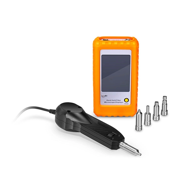
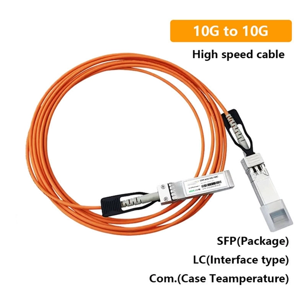
Find and discover Relay manufacturers and suppliers for all products in Ghana, featuring details on their shipment activities, trade volumes, trading partners, and more. View all relay buyers based on products in Ghana. Complete range of panel assembly components and equipment for electrical installations. Professional electrical testing and measurement instruments for accurate diagnostics and safety checks. Subscribe to global trade data intelligence to discover new business. Automation & Plant Technologies Limited (APT) specializes in providing high-quality electrical solutions tailored to meet the needs of various industries. Our expertise covers power distribution, automation, and energy management, ensuring that businesses achieve optimal performance and cost. Automation Ghana supplies all types of electrical and control cables, including the full HELUKABEL range, and provides tailored cable management solutions—from cable trays and conduits to routing and installation. Our protection relays and circuit breakers safeguard your systems from overloads. Services Merchandize Limited was established in 1989 in Ghana – branches in Accra and Kumasi – We have since been involved in various building projects in supply of Switchgear and circuit protection equipment. We value relationships more than anything else. As a leading electric supplier and exporter in the UAE and Ghana, we specialize in delivering innovative and.
[PDF]
There are many types of protective relays, and each one is designed for a specific type of protection. Common types include overcurrent relay, differential relay, distance relay, earth fault relay, and under/over voltage relay. Protective Relay Definition: A protective relay is an automatic device that senses abnormal conditions in electrical circuits and triggers actions to isolate faults. Types of Protective Relays: Protective relays are categorized by their mechanism (electromagnetic, static, mechanical) and function. This article covers various types of protective relays, such as overcurrent, directional, and differential relays, highlighting their operating characteristics and applications in electrical systems. Its main purpose is to safeguard electrical equipment like transformers, generators, and transmission lines from damage due to. Understanding the different types of protective relays and the applications of differential relays is crucial for anyone involved in electrical engineering or maintenance. The selection of relay depends on the type of equipment and fault. The rectangular devices are test connection blocks, used for testing and isolation of instrument transformer circuits. : 4 The first protective relays were electromagnetic.
[PDF]
Using a multimeter, check continuity between the black connector and the marked pin of the optocoupler input that is not working. If there is no continuity, the possible causes are: Connect a 5 V to 24 V signal to the input being tested. Measure the voltage at the marked. Using a multimeter, you can perform several tests to assess the functionality of an optocoupler. Each test targets a specific aspect of the optocoupler's operation. An optocoupler is an essential electronic component that transfers signals without a direct electrical connection. more n this video, you will learn how to test an optocoupler (optoisolator) using a. Optocoupler is one type of ICs, It isolates input and output section by using optical technology this feature increase safety of circuit. Optocoupler has many part number, different part number has different output type so before checking it has to use part number to research with datasheet and. If any optically isolated input on the controller is not working, follow the steps below to identify the cause. For our demo purposes, we will be using the PC817, a commonly used transistor output optocoupler in electronics. An opto-isolator contains a source (emitter) of light, almost always a near infrared light-emitting diode (LED), that converts electrical input signal into light, a closed optical channel (also called dielectrical channel, and a photo sensor, which detects incoming light and either generates.
[PDF]
The electrical quantities that may change under fault conditions include: voltage, current, frequency and phase angle. As the protected components of the electrical systems have changed in size, configuration and their critical roles in the power system supply, some protection aspects need to be revisited (i. the use of protection systems to reduce arc flash energy in distribution systems). This presentation. In electrical engineering, a protective relay is a relay device designed to trip a circuit breaker when a fault is detected. : 4 The first protective relays were electromagnetic devices, relying on coils operating on moving parts to provide detection of abnormal operating conditions such as. The relays detect the abnormal conditions in the electrical circuits by constantly measuring the electrical quantities which are different under normal and fault conditions. A typical. Overcurrent relays are the most common form of protection used to operate only under fault conditions. The relay settings that are selected are often a compromise in order to cope with both overload and. Time-current characteristics, current setting, over current protective schemes, directional relay, protection of parallel feeders, protection of ring mains, Phase fault and earth fault protection, Combined earth fault and phase fault protective scheme, Directional earth fault relay.
[PDF]
Distance relays, also known as impedance relay, differ in principle from other forms of protection in that their performance is not governed by the magnitude of the current or voltage in the protected circuit but rather on the ratio of these two quantities.OverviewIn, a protective relay is a device designed to trip a when a is detected. The first protective relays were electromagnetic devices, relying on coils operating on moving par. Electromechanical protective relays operate by either, or. Unlike switching type electromechanical with fixed and usually ill-defined operating voltage thresholds. Electromechanical relays can be classified into several different types as follows: "Armature"-type relays have a pivoted lever supported on a hinge or knife-edge pivot, which carries a moving contact. These relays may.
[PDF]