Use this Protection Relay Setting Calculator to calculate pickup current, time multiplier settings (TMS), operating time, coordination time interval (CTI), and plug setting multiplier (PSM) using fault current, CT ratio, and IEC 60255 curve parameters. of protective relays in terms of protecting high voltage lines. At the beginn ng of the article it is drawn up process to protect power lines. Consequently, it is shown the method of calculation for a particular power line a d performed the calculation for setting the distance protection. These calculations are critical in industrial. ve reliable and properly coordinated relay settings. Protection coordination refers to the systematic arrangement and interaction of protective devices within an electrical distribution network to ensure that faults are isolated in a controlled and orderly manner. The. With the help of these spreadsheets below, you can make your endless calculations much easier! Contact us for more information and download:.
[PDF]
of relay protection coordination for a PV power plant connected to the distribution network is presented. In recent years, installation of PV power plants in the distribution network has increased significantly. I.
[PDF]
The document discusses the principles and philosophy of protective relaying in power systems, emphasizing its role in preventing equipment damage and improving system reliability. Following a review of power system equipment, students define common protection terms and use common IEEE device designations while performing acceptance tests on protective relay schemes and elements. Combined with logic statements and a breaker control scheme, students develop a coordinated. IEEE/IAS/I&CPSD Protection & Coordination WG Chair Jacobs Canada, Calgary, AB rasheek. com IEEE Southern Alberta Section PES/IAS Joint Chapter Technical Seminar - November 2016 Protective Relays - Technical Seminar Nov 2016 - Copyright: IEEE 2 Abstract: Protective relays and devices. Georgian DS is a station that is supplied from a 44 kV feeder with one 10. 0 MVA delta/wye transformer with Z=6. The rated voltage of the primary winding is 46. The Question: ELEC 3007 - Assignment 7 - Protection Co-ordination Study (50) Name: This assignment will involve the relay. The Multilin™ 8 Series platform of advanced protection and control relays delivers high quality and performance management, protection and control for transformer, generator, motor and feeder applications. It outlines the factors influencing protection schemes, the importance of designing systems for selectivity and speed.
[PDF]
A relay protection tester is a core device used to verify the performance of relay protection devices. Its working principle can be summarized as “signal excitation – behavior detection. ”. Circuit principle of relay protection tester 1, input AC220V power output control relay K1 is approved by the insurance into the dual voltage regulator for T1 input carbon brush, through large knob to adjust the power into the isolation transformer T1 T2 (part-time riser), heat flow device points. When the transformer wiring type is Y/Y (Y0), the test wiring is very simple: when testing phase A, the tester IA is connected to the phase A of the high voltage side, and the tester IB is connected to the phase a of the low voltage side. ” The tester has a built-in high-precision programmable power supply, capable of simulating various operating. This handbook covers the code of practice in protection circuitry including standard lead and device numbers, mode of connections at terminal strips, colour codes in multicore cables, dos and donts in execution. The following is a detailed summary. This Playlist is assigned to sessions of protection Relays Principles. First, a description of Simple Functions.
[PDF]
The relay block comprises the two protection units, phase protection unit and earth protection unit. When the value of the current in any of the phases is greater than the pick up value, the phase protecti.
[PDF]

This document provides a comprehensive technical overview of the Ring Main Unit (RMU), serving as a reference for power system design, selection, and maintenance. Ring Main Units (RMU s) and Medium Voltage (MV) Switchgear are crucial in MV power distribution. Globally, they each hold about half the market share. MV switchgear handles primary distribution for large industrial facilities and grid infrastructure. RMUs, however, shine in secondary distribution. RMUs are commonly used in secondary distribution systems, particularly in urban areas, industrial complexes, and commercial. Scope of Application: The Ring Main Unit (RMU) is a compact switchgear device used in medium-voltage power distribution systems (typically 10kV–35kV). Some of the key features of the RMU includes SF6 gas insulation, compact and modular construction, integral protection system, fully extendable options. SFA-RM units are designed for supplying reliable energy, protecting electrical equipment in secondary distribution networks up to 17. Their compact design makes them suitable for various network applications such. Loading. Company Introduction:The New Concept Electric Inc. (NCE) was founded in October 2001, with a registered capital of 57 million Yuan. The company now covers an area of 77, 601 square meters (116 acres), and has a building area of 80, 451 square meters.
[PDF]
Thermal overload relays are widely used to protect motors. These devices work on the thermal effect principle. A thermal relay is an electromechanical device that detects temperature changes in electrical circuits, protecting equipment from overload and overheating. Thermal relays are critical components in electrical systems, designed to protect motors and other electrical equipment from damage caused by. Thermal Relay Definition: A thermal relay is defined as a device that uses the unequal expansion rates of metals in a bimetallic strip to detect overcurrent conditions. Working Principle: The thermal relay operates by heating a bimetallic strip, causing it to bend and close normally open contacts. So, the thermal relay is one of the types of the relay, used to provide complete safety against single phasing, unbalanced voltages & overloads. Thermal relays are the perfect solution for providing protection to motors which provides the most precise tripping for the electric motor during single. Introduction — The Core Device Protecting Industrial Motors Thermal overload relays are one of the most essential protection components in industrial motor circuits. Correct understanding and configuration ensure equipment safety and longevity. Its performance matches the actual heating characteristics of.
[PDF]
The standard industry practice is to set overload relays at 125% of the motor's nameplate Full Load Ampere (FLA) rating. Plug Setting Multiplier (PSM) indicates how many times the determined relay secondary current (typically the CT secondary) exceeds the relay pickup (plug) current. It is the key quantity utilized in IDMT (inverse definite minimum time) curves to calculate the basic operating time. PSM (Plug Setting. An overload relay is a crucial device for motor control, designed to prevent motors from overheating or suffering winding damage due to excessive current. Motor overload relays protect against sustained overcurrent conditions that cause dangerous overheating, insulation breakdown, and premature. Overload relays protect motors and equipment from thermal damage caused by prolonged overcurrent conditions. IEC 60255 defines standards, formulas, and performance requirements, enabling accurate calculations and real-world applications. How is the overload relay current calculated? Why include. Setting motor overload relays correctly is critical for protecting AC induction motors from sustained overcurrent conditions while avoiding nuisance trips during normal starting transients. This occurred when the relay F was set at 1. The complaint was that the relay tripped instantly on overload when the thermal damage curve show plotted for a specific current that was less t an.
[PDF]
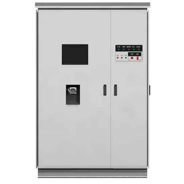
An analog accessory for use in a system for testing protection relays is provided, comprising inputs connectable to the current outputs of a test-set for protection relays and voltage outputs connectable to a protection relay to be tested. The register contains national patents and information related to European Patents validated in Malta. It currently provides European patent numbers, filing dates, titles, abstracts, classifications, applicants, bibliographic data, status, priorities, expirations, annuity/renewal fees. The utility model discloses a power plant relay protection tester, belonging to the technical field of relay protection testers, which comprises a relay protection tester body and a shell for placing the relay protection tester body, wherein a partition plate is arranged in the shell, a driving. Application to amend a patent application or registration. Convert a European patent application to a National patent. Request an extension of a time limit for the submission of patent documents. By providing an electric circuit adapted to convert current. Background Relays and metering are an important part of power generation, power transmission, and power con- sumption in electric power systems and the power grid. Relays provide monitoring and protection of equipment and personnel.
[PDF]
Free electrical load calculation tool for residential and commercial buildings. Calculate service entrance sizing, panel loads, demand factors, and ensure NEC Article 220 compliance. A sub panel is a secondary distribution point, fed from the main service panel, that provides a local hub for additional circuit breakers and wiring. Always verify calculations with a. The NEC (National Electrical Code) provides guidance on how to size wires correctly for feeders and subpanels. These rules change slightly from one edition to the next. This guide focuses on NEC 2023 standards. Choosing the correct subpanel wire size ensures safety, prevents overheating, and keeps. How to Size a Subpanel or Main Lug? For load calculation, multiply continuous loads (lasting 3 or more hours, e., water heaters) by 125% per NEC 310-14 and add 100% of non-continuous loads (like light bulbs, TVs). Total Load = 125% * Continuous Loads + 100% * Non-Continuous Loads To account for. URD cable, short for Underground Residential Distribution Cable, is a type of low-voltage power cable used in secondary power distribution networks. to by meter, Legacy the size is sizes sized of the include based main 60A on breaker. Common of The the main meter sizes breaker. socket, When main impacting new residential legacy breaker, knob electrical loads are added, available capacity.
[PDF]
This study aims to develop a simple yet efficient performance-based design optimization methodology for cable tray systems in building structures. In the paper, the drift ratio between adjacent supports i.
[PDF]
The SEL-221F Relay uses positive-sequence memory voltage polarized mho distance elements for phase and ground distance protection. These elements expand in proportion to the source impedance to provide more resistive fault coverage than self-polarized mho elements. VAMP 221 arc protection system components. Central unit VAMP 221. I/O units VAM 12L / VAM 12 LD, VAM 10L / VAM 10LD, VAM 3L / VAM 3LX and VAM 4C / VAM 4CRL / VAM 4CD 10 1. Arc sensors VA 1 DA, VA 1 EH, ARC SLx. Schneider Electric VAMP range is an arc flash detection and protection pioneer offering fast and reliable devices to improve safety. VAMP 221 significantly reduces the risk of potential personal damage, and material and production losses caused by arc fault. VAMP 221 complies with the latest standards concerning the. Serial communications ports allow local or remote interaction with the relay. 5” high chassis sizes. The report will identify methodology behind these practices, present issues raised by the integration of microprocessor relays and the internal logic and external communication configurations, ying. In the design of electrical power systems, the ANSI Standard Device Numbers denote what features a protective device supports (such as a relay or circuit breaker).
[PDF]
With its novel and future-oriented approach our software solution for system-based protection testing, performs tests independent of relay type, relay manufacturer, and offers extensive parameter settings. It focuses on. With its novel and future-oriented approach our software solution for system-based protection testing, performs tests independent of relay type, relay manufacturer, and offers extensive parameter settings. It focuses on the correct behavior of the protection system by simulating realistic events in the power system. RelaySimTest. Specifically designed for settings-based protection testing with a high degree of automation, our modular software Test Universe offers numerous functions and application-optimized test modules that save you valuable time. Test Universe. Use CMControl P for quick and easy manual testing. CMControl P is available as an App for Android tablets and Windows PC, or as a dedicated front-end device. CMControl P. With this software the CMC test set becomes a multifunctional measurement and recording unit. You can use EnerLyzer in parallel with the software used for operating your CMC. Enerlyzer. The open programming interface CMEngine enables you to integrate the CMC test sets into your own testing environment and control them within any type of application. CMEngine.
[PDF]
What is the cost of a relay coordination study in Singapore ? The cost of a protective device study in Singapore depends on the complexity of the electrical system, facility size, and number of relays. I2R, as a firm of Professional Engineers and Licensed Electrical Workers, is qualified under the Electricity Act to carry out all types of electrical testing and commissioning works to ensure that electrical apparatus are fit for power energization and safe for use and operation. We have all the. We are Specialized in Low Voltage Switchgears Testing, Commissioning, Maintenance and Installations from OEM's. We do factory Acceptance and Site Acceptance Testing and Commissioning support of LV Switchgears. Earth loop impedance measurments. Care Offers cost-effective solutions for protective device coordination in compliance with. Advance Engineering and Testing (AET) Pte Ltd established on 2019, is a top provider of electrical testing ranging from commercial, domestic, and industrial. The company provides 24/7 onsite support with prioritization of customer satisfaction. Their vision and mission statement is to continuously. The type of testing required for each specific relay needs to be designed with the goal of accomplishing the objective. We perform testing in four specific classes which. Our services are applicable to a number of industries such as Petrochemical industries, Oil and gas fabrication industries, Wafer fabrication plants, Pharmaceuticals.
[PDF]
In this guide, we'll explore what protection relays are, how they're classified, the types available, and how they work with instrument transformers to create secure zones of protection. What Is a Protection Relay?. Protective Relay Definition: A protective relay is an automatic device that senses abnormal conditions in electrical circuits and triggers actions to isolate faults. Types of Protective Relays: Protective relays are categorized by their mechanism (electromagnetic, static, mechanical) and function. This article covers various types of protective relays, such as overcurrent, directional, and differential relays, highlighting their operating characteristics and applications in electrical systems. They don't just protect equipment; they ensure safety, prevent downtime, and save lives. A protective relay is a device that detects the fault and initiates the operation of the circuit breaker to isolate the defective element from the rest of the. The rectangular devices are test connection blocks, used for testing and isolation of instrument transformer circuits.
[PDF]