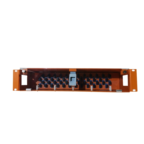
There are many types of protective relays, and each one is designed for a specific type of protection. Common types include overcurrent relay, differential relay, distance relay, earth fault relay, and under/over voltage relay. Protective Relay Definition: A protective relay is an automatic device that senses abnormal conditions in electrical circuits and triggers actions to isolate faults. Types of Protective Relays: Protective relays are categorized by their mechanism (electromagnetic, static, mechanical) and function. This article covers various types of protective relays, such as overcurrent, directional, and differential relays, highlighting their operating characteristics and applications in electrical systems. Its main purpose is to safeguard electrical equipment like transformers, generators, and transmission lines from damage due to. Understanding the different types of protective relays and the applications of differential relays is crucial for anyone involved in electrical engineering or maintenance. The selection of relay depends on the type of equipment and fault. The rectangular devices are test connection blocks, used for testing and isolation of instrument transformer circuits. : 4 The first protective relays were electromagnetic.
[PDF]
The document discusses the principles and philosophy of protective relaying in power systems, emphasizing its role in preventing equipment damage and improving system reliability. Following a review of power system equipment, students define common protection terms and use common IEEE device designations while performing acceptance tests on protective relay schemes and elements. Combined with logic statements and a breaker control scheme, students develop a coordinated. IEEE/IAS/I&CPSD Protection & Coordination WG Chair Jacobs Canada, Calgary, AB rasheek. com IEEE Southern Alberta Section PES/IAS Joint Chapter Technical Seminar - November 2016 Protective Relays - Technical Seminar Nov 2016 - Copyright: IEEE 2 Abstract: Protective relays and devices. Georgian DS is a station that is supplied from a 44 kV feeder with one 10. 0 MVA delta/wye transformer with Z=6. The rated voltage of the primary winding is 46. The Question: ELEC 3007 - Assignment 7 - Protection Co-ordination Study (50) Name: This assignment will involve the relay. The Multilin™ 8 Series platform of advanced protection and control relays delivers high quality and performance management, protection and control for transformer, generator, motor and feeder applications. It outlines the factors influencing protection schemes, the importance of designing systems for selectivity and speed.
[PDF]
Thermal overload relays are widely used to protect motors. These devices work on the thermal effect principle. A thermal relay is an electromechanical device that detects temperature changes in electrical circuits, protecting equipment from overload and overheating. Thermal relays are critical components in electrical systems, designed to protect motors and other electrical equipment from damage caused by. Thermal Relay Definition: A thermal relay is defined as a device that uses the unequal expansion rates of metals in a bimetallic strip to detect overcurrent conditions. Working Principle: The thermal relay operates by heating a bimetallic strip, causing it to bend and close normally open contacts. So, the thermal relay is one of the types of the relay, used to provide complete safety against single phasing, unbalanced voltages & overloads. Thermal relays are the perfect solution for providing protection to motors which provides the most precise tripping for the electric motor during single. Introduction — The Core Device Protecting Industrial Motors Thermal overload relays are one of the most essential protection components in industrial motor circuits. Correct understanding and configuration ensure equipment safety and longevity. Its performance matches the actual heating characteristics of.
[PDF]
Find and discover Relay buyers & importers for all products in Benin, featuring details on their shipment activities, trade volumes, trading partners, and more. View all relay suppliers based on products in Benin. How does 6Wresearch market report help businesses in making strategic decisions? 6Wresearch actively monitors the Benin Protective Relays Market and publishes its comprehensive annual report, highlighting emerging trends, growth drivers, revenue analysis, and forecast outlook. Our insights help. There are 72 Manufacturers in Benin as of April 1, 2026; which is an 9. 09% increase from 2023. The top three states with the most Manufacturers are Atlantique Department with 20 Manufacturers, Borgou Department with 14 Manufacturers, Littoral Department with 11 Manufacturers. Subscribe to global trade data intelligence to discover new business opportunities. Top 10 Companies in Benin: A Profile of Industry Leaders Benin, a coastal nation in West Africa, has witnessed significant economic growth in recent years. The country's business landscape is dominated by a diverse range of companies, spanning various industries and contributing to its overall. It is bordered by Togo to the west, Nigeria to the east, and Burkina Faso and Niger to the north. A majority of the population live on its small southern coastline on the Bight of Benin, part of the Gulf of Guinea in the northernmost tropical portion of the Atlantic Ocean. This report offers comprehensive.
[PDF]

Thinner cables can be utilized to connect the control switch to the relay; this saves space, weight, and cost. The same voltage and current ratings as other types of switches, such as mechanical switches, do not limit relays. This handbook covers the code of practice in protection circuitry including standard lead and device numbers, mode of connections at terminal strips, colour codes in multicore cables, dos and donts in execution. Also principles of various protective relays and schemes including special protection. A control relay is an electrically operated switch that enables current to flow through a coil that closes or opens the switch. Relays use a small current to control a larger current, making them ideal for controlling high-power devices such as motors, lights, valves, and sensors. When a relay contact is open, this will switch power ON for a circuit when the coil is activated. You'll connect a low-power control circuit to the relay's coil (terminals 85 and 86), which then flips a switch for a separate, high-power circuit running through the. Electrical protection relay has two type protecton as HT panel protection and LT panel protection. HT panel protection relay. The HT power supply is received from GO switch and distributed to the. The rectangular devices are test connection blocks, used for testing and isolation of instrument transformer circuits. : 4 The first protective relays were electromagnetic.
[PDF]
Protection: CVTs supply voltage signals to protective relays, enabling them to detect faults and initiate appropriate actions, such as circuit breaker tripping. Control: CVTs can also be used in control systems to monitor voltage levels and provide feedback for voltage regulation. Capacitive Voltage Transformers (CVTs) are common in high-vo tage transmission line applications. These same applications require fast, yet secure protection. However, as the requirement for faster protective relays grows T models whose purpose is to identify which major CVT components contribute. ve Voltage (CVT) and Capacitance Coupled Voltage Transformers (CCVT). With this comprehensive range of accurate power sensing devices coupled with GE's vertical integration approach and skilled design engineering staf, we work closely with our globa ems for applications ranging from high-voltage to. Capacitive Voltage Transformers (CVTs), also known as capacitor voltage transformers, are essential components in high-voltage power systems. They provide a cost-effective and reliable means of measuring voltage and supplying power to protective relays and metering equipment. This essay will delve. Potential transformers and coupling capacitor voltage transformers (CCVT's) have been used successfully for providing voltage to the inputs of meters and relays since the 1960's. It utilizes a capacitive voltage divider in conjunction with an electromagnetic voltage converter to provide a.
[PDF]
If a fault is detected, the relay will send signals to adjacent relays and circuit breakers, allowing the closest breaker to trip first while other breakers delay their operation. This selective coordination helps isolate the faulted zone while maintaining the power supply to the. A protection relay is a crucial component of electrical systems that safeguard infrastructure, employees, and equipment from electric problems and malfunctions. It functions as a watchdog by constantly surveying multiple system components including voltage, current, frequency, and phase angle. It. A protective relay is the vigilant guardian of electrical networks, constantly monitoring and analyzing electrical parameters to detect abnormal events. Acting as the first line of defence, it swiftly detects faults, such as short circuits or overcurrents. It triggers protective actions to isolate. In electrical engineering, a protective relay is a relay device designed to trip a circuit breaker when a fault is detected. : 4 The first protective relays were electromagnetic devices, relying on coils operating on moving parts to provide detection of abnormal operating conditions such as. A protective relay is an intelligent device that senses abnormal electrical conditions, such as overcurrent, under-voltage, or frequency deviations. It initiates the operation of circuit breakers to isolate the affected section.
[PDF]
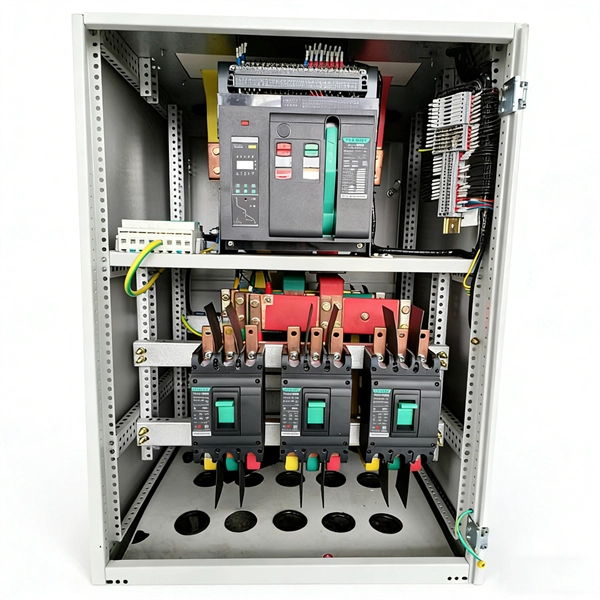
By breaking power into smaller, manageable loads, the box ensures consistent delivery while protecting each circuit from overload. Inside, it houses circuit breakers, busbars, and terminals that collectively control and protect electrical flow. Correct wiring methods for circuit breakers within distribution boxes are fundamental to ensuring electrical safety and compliance with established codes. The distinction between 1P and 2P circuit breakers plays a pivotal role in determining the appropriate protection level for various circuits. What is the distribution box? A. A distribution board (DB) is the central component of any power distribution system, providing a safe and organized way to deliver electricity from the main supply to individual circuits. Understanding its significance. A distribution box is a vital piece of equipment that ensures the effective and safe distribution of electrical power in various parts within a building or complex. It is widely employed in residential, commercial and industrial set-ups for circuit control and protection. By knowing their great.
[PDF]
Home distribution boxes typically handle single-phase power supplies and contain 6 to 24 circuits. They include standard circuit breakers for lighting, outlets, and major appliances like water heaters and air conditioning units. You lower the chance of circuits getting too hot or overloaded when you pick the right box for your needs. You leave space for safety devices like circuit breakers and surge protectors. Example: Need a circuit for your 1,800W microwave? Calculator Tip: Tools like Desmos' scientific calculator make light work of conversions. Just plug in your wattage and voltage—let it handle the decimals. You're not just calculating numbers—you're designing a system that matches how you live. A smaller, compact box with standard circuit breakers is typically sufficient for household needs, where power demand is relatively low. Commercial Buildings: In offices or. Covers general-purpose lighting circuits, small appliance circuits, laundry circuits, dedicated appliance circuits, and 240V equipment circuits for complete home electrical design. Calculations are for reference only. Always verify against NEC and local codes before installation. Consult a. A distribution box, also known as a power distribution box or electrical distribution box, is used to distribute electrical power safely to multiple circuits. It helps organize, protect, and control electrical connections in residential, commercial, and industrial electrical systems. Let us look at the.
[PDF]
Find and discover Relay manufacturers and suppliers for all products in Ghana, featuring details on their shipment activities, trade volumes, trading partners, and more. View all relay buyers based on products in Ghana. Complete range of panel assembly components and equipment for electrical installations. Professional electrical testing and measurement instruments for accurate diagnostics and safety checks. Subscribe to global trade data intelligence to discover new business. Automation & Plant Technologies Limited (APT) specializes in providing high-quality electrical solutions tailored to meet the needs of various industries. Our expertise covers power distribution, automation, and energy management, ensuring that businesses achieve optimal performance and cost. Automation Ghana supplies all types of electrical and control cables, including the full HELUKABEL range, and provides tailored cable management solutions—from cable trays and conduits to routing and installation. Our protection relays and circuit breakers safeguard your systems from overloads. Services Merchandize Limited was established in 1989 in Ghana – branches in Accra and Kumasi – We have since been involved in various building projects in supply of Switchgear and circuit protection equipment. We value relationships more than anything else. As a leading electric supplier and exporter in the UAE and Ghana, we specialize in delivering innovative and.
[PDF]
With its novel and future-oriented approach our software solution for system-based protection testing, performs tests independent of relay type, relay manufacturer, and offers extensive parameter settings. It focuses on. With its novel and future-oriented approach our software solution for system-based protection testing, performs tests independent of relay type, relay manufacturer, and offers extensive parameter settings. It focuses on the correct behavior of the protection system by simulating realistic events in the power system. RelaySimTest. Specifically designed for settings-based protection testing with a high degree of automation, our modular software Test Universe offers numerous functions and application-optimized test modules that save you valuable time. Test Universe. Use CMControl P for quick and easy manual testing. CMControl P is available as an App for Android tablets and Windows PC, or as a dedicated front-end device. CMControl P. With this software the CMC test set becomes a multifunctional measurement and recording unit. You can use EnerLyzer in parallel with the software used for operating your CMC. Enerlyzer. The open programming interface CMEngine enables you to integrate the CMC test sets into your own testing environment and control them within any type of application. CMEngine.
[PDF]
Ungrounded: There is no intentional ground applied to the system-however it's grounded through natural capacitance. Reactance Grounded: Total system capacitance is cancelled by equal inductance. This decreases the current at the fault and limits voltage across the arc at the. In electrical engineering, a protective relay is a relay device designed to trip a circuit breaker when a fault is detected. : 4 The first protective relays were electromagnetic devices, relying on coils operating on moving parts to provide detection of abnormal operating conditions such as. To attain the desired reliability, the power system network is divided into two different protection zones. They are generator protection, transformer protection, bus protection, transmission line protection and feeder. Recognized under 2(f) and 12 (B) of UGC ACT 1956 (Affiliated to JNTUH, Hyderabad, Approved by AICTE - Accredited by NBA & NAAC – 'A' Grade - ISO 9001:2015 Certified) Maisammaguda, Dhulapally (Post Via. Kompally), Secunderabad – 500100, Telangana State, India To introduce all kinds of circuit. A protection relay is a crucial component of electrical systems that safeguard infrastructure, employees, and equipment from electric problems and malfunctions. It functions as a watchdog by constantly surveying multiple system components including voltage, current, frequency, and phase angle.
[PDF]
IEC 60255-1:2022 specifies common rules and requirements applicable to measuring relays and protection equipment, including any combination of equipment to form a distributed protection scheme for power system protection such as control, monitoring and process interface equipment . IEC 60255-1:2022 specifies common rules and requirements applicable to measuring relays and protection equipment, including any combination of equipment to form a distributed protection scheme for power system protection such as control, monitoring and process interface equipment . The IEC standard for protection relays plays a vital role in modern electrical power systems. Protection relays are essential devices used to detect abnormal conditions in electrical circuits. These conditions may include overloads, short circuits, or insulation failures. When such conditions are. The testing and verification of relay protection devices can be divided into four groups: Type tests are needed to prove that a protection relay meets the claimed specification and follows all relevant standards. Choose from interactive classroom training and hands-on. To meet this need, the IEC is currently working on the IEC 60255-1xx series of functional standards dedicated to protection relays and protection functions. Before looking at the benefits these standards can provide, let us review some background information.
[PDF]
The electrical quantities that may change under fault conditions include: voltage, current, frequency and phase angle. As the protected components of the electrical systems have changed in size, configuration and their critical roles in the power system supply, some protection aspects need to be revisited (i. the use of protection systems to reduce arc flash energy in distribution systems). This presentation. In electrical engineering, a protective relay is a relay device designed to trip a circuit breaker when a fault is detected. : 4 The first protective relays were electromagnetic devices, relying on coils operating on moving parts to provide detection of abnormal operating conditions such as. The relays detect the abnormal conditions in the electrical circuits by constantly measuring the electrical quantities which are different under normal and fault conditions. A typical. Overcurrent relays are the most common form of protection used to operate only under fault conditions. The relay settings that are selected are often a compromise in order to cope with both overload and. Time-current characteristics, current setting, over current protective schemes, directional relay, protection of parallel feeders, protection of ring mains, Phase fault and earth fault protection, Combined earth fault and phase fault protective scheme, Directional earth fault relay.
[PDF]
Use this Protection Relay Setting Calculator to calculate pickup current, time multiplier settings (TMS), operating time, coordination time interval (CTI), and plug setting multiplier (PSM) using fault current, CT ratio, and IEC 60255 curve parameters. of protective relays in terms of protecting high voltage lines. At the beginn ng of the article it is drawn up process to protect power lines. Consequently, it is shown the method of calculation for a particular power line a d performed the calculation for setting the distance protection. These calculations are critical in industrial. ve reliable and properly coordinated relay settings. Protection coordination refers to the systematic arrangement and interaction of protective devices within an electrical distribution network to ensure that faults are isolated in a controlled and orderly manner. The. With the help of these spreadsheets below, you can make your endless calculations much easier! Contact us for more information and download:.
[PDF]