LV overhead lines are protected against overcurrents using fuses or circuit breakers. Protection of MV overhead lines is usually achieved by overcurrent relays (50; 50N; 51; 51N; 67; 67N) connected to.
[PDF]
Download Sample Report Now: Global Protective Relays Market Size, Share, Trends & Forecast 2026-2034 The following comparison highlights how leading players differentiate across scale, strategy, and regional dominance. Protective relays are electrical devices that are designed to detect abnormal conditions in power systems and isolate the affected part of the system. Insight: Global leaders dominate through scale, while niche innovators gain. These companies offer protective relay devices for electrical systems, protecting them from overloads, short circuits, and other electrical faults. *Disclaimer: List of key companies in no particular order Latest Company Updates: October 2023- The PJM Board of Managers has permitted some. Over Current Relay (OCR): Operates when the current value at the location where the protective relays are installed exceeds the set value. There are two types of elements that trigger the overcurrent protective relays: dimensional elements and instantaneous elements. The dimensional element. The global protective relay market is expected to reach USD 3. 9 billion by 2030, up from an anticipated USD 2. 7% over the forecast period. The shift from traditional relays to advanced, software-driven systems in protective relays brings enhanced reliability. Moreover, according to Consegic Business Intelligence, Protective Relay Market size is estimated to reach over USD 5,093. 8% from 2025 to 2032.
[PDF]
Its main purpose is to safeguard electrical equipment like transformers, generators, and transmission lines from damage due to abnormal conditions such as overloads, short circuits, or voltage imbalances. A protective relay is an intelligent electrical device designed to detect faults in power systems and initiate corrective actions such as tripping a circuit breaker. It initiates the operation of circuit breakers to isolate the affected section. This prevents damage to equipment, reduces. Transmission lines are a vital part of the electrical distribution system, as they provide the path to transfer power between generation and load. Transmission lines operate at voltage levels from 69kV to 765kV, and are ideally tightly interconnected for reliable operation. In other words, the prime function of protective relays is the timely and. Many important issues, such as coordination of settings, operating times, characteristics of relays, mutual coupling of lines, automatic reclosing, and use of communication channels, are examined. Special protection systems, protection of multi-terminal lines, and single-phase tripping and. In electrical engineering, a protective relay is a relay device designed to trip a circuit breaker when a fault is detected.
[PDF]
Instantaneous overcurrent protection is where a protective relay initiates a breaker trip based on current exceeding a pre-programmed “pickup” value for any length of time. This is the simplest form of ov.
[PDF]
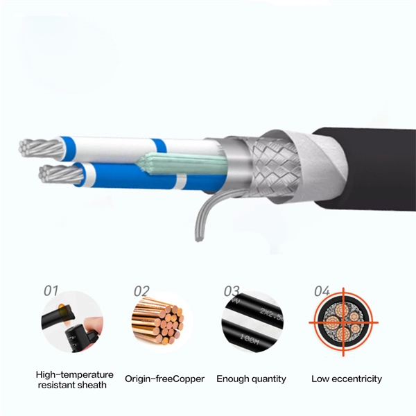
Join me in this concise video as I demonstrate the meticulous process of connecting stranded wires in a junction box through soldering. Whether you're a DIY enthusiast or a professional electrician, this brief tutorial offers valuable insights into using soldering for. I was changing a switch in my house when I found a number of connections in the electrical box that were soldered rather than secured with a wire nut. The solder joints look very well done, the conductors were twisted together nicely and the solder itself was nicely done. It was not some oxidized. I have found several soldered wires inside junction boxes in my older lake house. I see mostly neutrals this way with the hots going to outlets or switches where they are looped onto the screws. If I am upgrading the junction box to a larger one I just cut the. I don't know why anyone would do this now a days but thats the interesting thing about being an inspector. I inspected a house today that someone is wiring the old school way. The grounds he used wire nuts on. more Join me. Because of different characteristics of dissimilar metals, devices such as pressure terminal or pressure splicing connectors and soldering lugs shall be identified for the material of the conductor and shall be properly installed and used. No wiring systems of any.
[PDF]
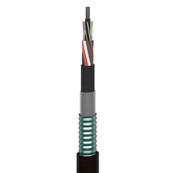
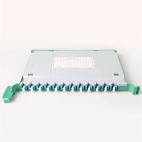
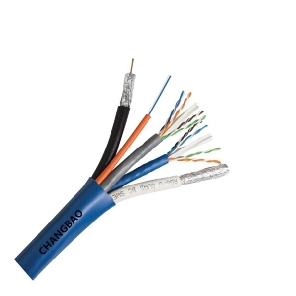
Fiber coating is a crucial component in the manufacture and operation of optical sensors. It refers to the thin layer of material applied to the surface of an optical fiber to protect it from environmental factors and enhance its performance. Optical fibers are thin strands of glass or plastic that transmit light signals over long distances. They are widely used in telecommunications, data networks, medical imaging, and sensing applications. However, optical fibers are also vulnerable to damage from various sources, such as bending. Within this blog we will combine the protection technology experience of Shanghai Leiditech Electronic, to reveal the key points and solutions for electrostatic surge protection in the circuit systems of optical fiber sensors. The optical fiber sensor circuit system mainly consists of a light. Fiber optic cables enable high-speed, long-distance data transfer, forming the backbone of modern communication. Yet, outdoors, they face temperature swings, moisture, UV exposure, rodents, and human interference. Protecting them is essential for long-term reliability. This guide covers how to. Accidental damage to fiber optic strain sensors can occur in a variety of ways. As an example, in the instrumentation of large test articles such as an aircraft wing, the low sensor profile makes it easy for its presence to be overlooked.
[PDF]

Relay testing involves verifying the correct operation of protective relays under various fault conditions. This process ensures that the relays provide accurate and timely tripping signals to circuit breakers, isolating the faulty sections of the electrical network. Protective circuit functional testing, including lockout relay testing, must take place immediately upon installation, every 2 years thereafter, and upon any change in wiring. If applicable, documentation is required detailing how verified protection segments overlap to ensure there is not a gap. Relay systems protect high-voltage equipment and transmission lines to ensure safe, stable systems. Although failure of a protective relay system may have severe local or regional impacts, most protective relay systems are not required to operate to prove they are in working order. Ensuring that. Relay testing and maintenance are crucial aspects of ensuring the reliability and stability of power systems. Protective relays play a vital role in detecting and isolating faults in electrical networks, thereby safeguarding expensive equipment and preventing cascading failures. This guide provides recommended. Protective relaying aims to stop that chain reaction before it starts, detecting problems instantly, cutting off the affected section, and keeping the rest of the system stable and safe. A good preventive maintenance program ensures the protection system is in functioning order.
[PDF]
Distance relays, also known as impedance relay, differ in principle from other forms of protection in that their performance is not governed by the magnitude of the current or voltage in the protected circuit but rather on the ratio of these two quantities.OverviewIn, a protective relay is a device designed to trip a when a is detected. The first protective relays were electromagnetic devices, relying on coils operating on moving par. Electromechanical protective relays operate by either, or. Unlike switching type electromechanical with fixed and usually ill-defined operating voltage thresholds. Electromechanical relays can be classified into several different types as follows: "Armature"-type relays have a pivoted lever supported on a hinge or knife-edge pivot, which carries a moving contact. These relays may.
[PDF]
High voltage relays are essential components in electrical systems. They control the flow of electricity in high voltage applications, enabling safe operations. These relays act as switches that open or close circuits. Their design ensures they handle high current levels without. Explore principles and configurations of protective relaying in high voltage systems. Ensure fast, selective fault clearance per IEC/IEEE standards. Protective relaying is the backbone of fault detection and system isolation in As transmission systems grow increasingly complex with integration of. A voltage protection relay system is a necessary component of any electrical setup. It prevents safety hazards and damage to equipment. It monitors voltage to determine if levels rise too high or dip too low. Many industries use voltage protection relay systems, especially those in high-voltage. Eaton's protective relays provide you with unique microprocessor-based devices that eliminate unnecessary trips, mitigate arc faults, protect motors and breakers, and provide system information to help you better manage your system. Our predictive diagnostic solutions include non-destructive testing. In electrical engineering, a protective relay is a relay device designed to trip a circuit breaker when a fault is detected. They are intended to quickly identify a fault and isolate it so the balance of the system continue to run under normal conditions.
[PDF]
Use this Protection Relay Setting Calculator to calculate pickup current, time multiplier settings (TMS), operating time, coordination time interval (CTI), and plug setting multiplier (PSM) using fault current, CT ratio, and IEC 60255 curve parameters. of protective relays in terms of protecting high voltage lines. At the beginn ng of the article it is drawn up process to protect power lines. Consequently, it is shown the method of calculation for a particular power line a d performed the calculation for setting the distance protection. These calculations are critical in industrial. ve reliable and properly coordinated relay settings. Protection coordination refers to the systematic arrangement and interaction of protective devices within an electrical distribution network to ensure that faults are isolated in a controlled and orderly manner. The. With the help of these spreadsheets below, you can make your endless calculations much easier! Contact us for more information and download:.
[PDF]
Ungrounded: There is no intentional ground applied to the system-however it's grounded through natural capacitance. Reactance Grounded: Total system capacitance is cancelled by equal inductance. This decreases the current at the fault and limits voltage across the arc at the. In electrical engineering, a protective relay is a relay device designed to trip a circuit breaker when a fault is detected. : 4 The first protective relays were electromagnetic devices, relying on coils operating on moving parts to provide detection of abnormal operating conditions such as. To attain the desired reliability, the power system network is divided into two different protection zones. They are generator protection, transformer protection, bus protection, transmission line protection and feeder. Recognized under 2(f) and 12 (B) of UGC ACT 1956 (Affiliated to JNTUH, Hyderabad, Approved by AICTE - Accredited by NBA & NAAC – 'A' Grade - ISO 9001:2015 Certified) Maisammaguda, Dhulapally (Post Via. Kompally), Secunderabad – 500100, Telangana State, India To introduce all kinds of circuit. A protection relay is a crucial component of electrical systems that safeguard infrastructure, employees, and equipment from electric problems and malfunctions. It functions as a watchdog by constantly surveying multiple system components including voltage, current, frequency, and phase angle.
[PDF]
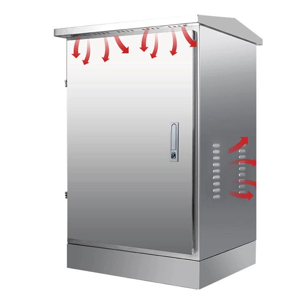
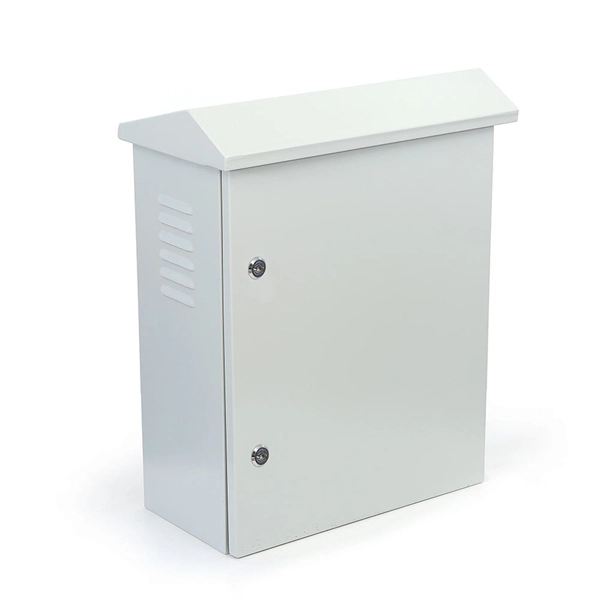
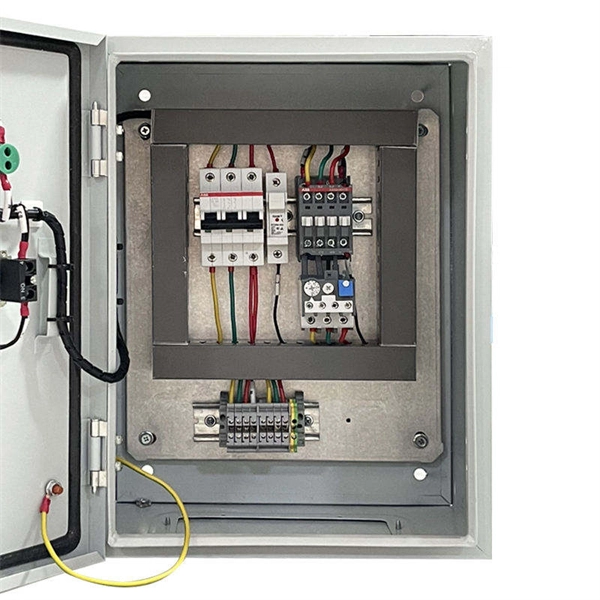
In this electrical room sizing example, learn how to size the room and position the equipment to meet NEC requirements. Electrical enclosure sizes are not universal, but most manufacturers follow common size families. This guide explains typical wall-mount and floor-standing dimensions, how to read catalog sizes, and how to choose the right enclosure size for your layout. Figure 6: Electric room sizes using the 2023 edition of the NEC are larger in design because clearances listed in Table 110. 26 (A) (1) need to be met plus the additional egress. Enclosure size includes external dimensions (for installation space) and internal space (for component layout and heat dissipation). Larger enclosures may be needed for outdoor use, better protection, or cooling components like fans or vents. Use 20–30% extra space for airflow and upgrades, and. Large electrical power distribution boxes come in several sizes—single-gang for one device, double-gang for two, and so on. Check out this quick guide: Think about how many devices you need, where you will install the box, and the environment. Picking the right size helps you stay safe, follow. This guide explores control panels, electrical boxes, breaker panels, bus bars, junction boxes, and custom enclosures to help you understand their sizes, types, and common applications. Used in industrial automation and process control. Houses PLCs, relays, contactors, and wiring. Supports control.
[PDF]
In this step-by-step guide, I'll show you how to install different types of rework (old work) electrical boxes in existing drywall. Whether you're adding a new outlet, light switch, or fixture, understanding the right electrical box for the job is crucial for a safe and. They are secured with clamps that are built into the box. Installing a remodeling box is something you can easily do with just a few tools. The step-by-step instructions detail the process of placing a plastic remodeling box in drywall for a. Remodelling an electrical box can seem like a daunting task, but with the right tools and knowledge, it can be a manageable project for homeowners. Learn how to install a distribution box safely and correctly. Covers wiring, placement, standards, and expert tips for a compliant setup. It takes the incoming power and safely distributes it to different circuits throughout your building. Before installing a new electrical box in your home, ensure that the power is turned off at your circuit breaker panel box and use a voltage tester to ensure safety. The process of installing a remodeling box, also known as a gem box, utility box, or handy box, involves removing an existing. Electrical boxes are foundational components of a home's wiring system, serving as protective enclosures where electrical connections are made and devices like switches or receptacles are mounted.
[PDF]
This report provides a comprehensive analysis of electrical distribution board (DB) box sizes, including physical dimensions, electrical capacities, and market trends based on current 2025-2026 standards. This guide helps you determine the correct dimensions based on wire fill capacity, device requirements, and installation environment, ensuring a safe and efficient electrical system. Selecting the appropriate junction box size prevents overcrowding, overheating, and potential hazards. Learn how to. Choosing the correct electrical box dimensions is essential for safe wiring, code compliance, and long-term reliability. NEC Article 408 covers switchboards, switchgear, and Panelboards installation and applications. Electrical enclosure sizes are not universal, but most manufacturers follow common size families. This guide explains typical wall-mount and floor-standing dimensions, how to read catalog sizes, and how to choose the right enclosure size for your layout. There is no single global chart for standard. stallation and use of boxes. The article includes table references that guide the electrician in the selection of the proper box size necessary to safely accommodate ele trical service requirements.
[PDF]
Finding the best electrical boxes for your home renovation or redo is vital. The right material, type, and size can increase security while eliminating the risk associated with house fires due to short circuit pr.
[PDF]