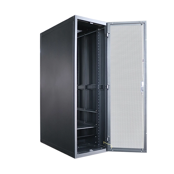
A server rack is a standardized metal enclosure designed to mount IT equipment—servers, switches, routers, PDUs, UPS systems, storage devices, patch panels, and cable managers—using vertical rails spaced according to the EIA-310 19-inch standard. What is a Server Rack? A server rack is specially designed to store various networking devices, which can effectively organize, manage, and protect network equipment including servers, network switches, routers, UPS, storage devices, etc., ensuring the stable and reliable operation of equipment. There are three primary rack types - open-frame racks, enclosed cabinets, and wall-mount racks, each suited for. The server rack is designed to house, organize and secure servers, networking equipment and other IT hardware. It provides efficient cable management, air flow and physical protection for sensitive electronic devices. Learn more about how airflow affects server performance in our detailed guide on how airflow works inside a. Hot and cold air containment systems designed to maximize cooling predictability, capacity, and efficiency at the rack, row or room level. Intelligent air containment solutions that protect critical IT equipment and personnel. Server racks come in a variety of sizes and configurations, ranging from small desktop units to large floor-standing.
[PDF]
In this guide, we'll explore top network rack options like the TECMOJO 12U Open Frame Network Rack and the ECHOGEAR 10U Network Rack. We will also cover features to consider, such as size, mounting style, and additional accessories. The 42U AV rack mount comes with thermostat, LCD screen, cooling fans, dust-tight cable entries, powerbar, casters, shelf, and fully locking cabinet doors and side panels. Ubuy works hard to protect your security and privacy. Our advanced payment security system ensures confidentiality by. Rack para servidor My Connection 8u. ULTIMOS! New and used Network Server Racks for sale in Montevideo, Uruguay on Facebook Marketplace. Find great deals and sell your items for free. A network rack is essential for organizing and securing your IT and AV equipment. Whether you need a wall-mounted or floor-standing rack, the right choice can make a big difference in your setup.
[PDF]
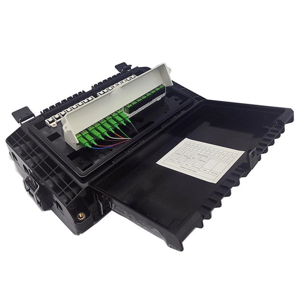
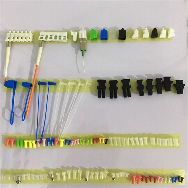
The most common and effective solution is the preformed tension clamp. This fitting consists of a set of helical rods that are wrapped around the cable, a thimble (clevis), and an extension link. The helical rods are designed to transfer the tensile load from the cable to the anchor. The function of the remaining cable rack is to store reserved optical cables, which are generally used on tensile towers (poles). There are two types: Inner button and outer disc. When the remaining cable rack is used for installation on the iron tower, it is equipped with two small splints. Additionally, adapters are available for the steel towers and steel and concrete poles. maintain alignment of and. ficing corrosion resistance. It is best suited to applications with moderate to low span ut increasing fibre strain. 3mm2 RRU Power cable. Without additional adapters, these clamps can provide sturdy, reliable, long-term support to systems. We manufacture a wide range of hardware fittings for OPGW Optical Ground Wire, including Suspension and Tension Assemblies, Down Lead clamps, Earthing Clamps, Splice Enclosure, Reinforcing Rods, Vibration Dampers, etc. Find many great new & used options and get the best deals for 5x Huawei Optical Cable Fixing Clamp 2x3 C Type Bracket Cable Clamp 27150086 at the best online prices at eBay! Free shipping for many products!.
[PDF]
In this video, we'll walk you through the process of wiring a home distribution box with a detailed connection diagram. Understanding the cable TV house wiring diagram can be helpful when troubleshooting connection issues or setting up new TV sets in your home. Whether you're an electrician or a DIY enthusiast, this guide will help you understand the basics of home electrical distribution. more Welcome to our channel! In this video. This course was adapted from the Department of Energy, Publication No. DOE-HDBK-1011/2-92, “Electrical Science”, Module 15, which is in the public domain. Gussow, Milton, Schaum's Outline Series. Distribution board is a safe system designed for house or building that included protective devices, isolator switches, circuit breaker and fuses to safely connect the cables and wires to the sub circuits and final sub circuits including their associated Live (Phase) Neutral and Earth conductors. Once this is identified, the wiring diagram should be drawn up, showing the main power line coming from the utility source and then branching off to the various branch circuits. This diagram should also indicate the type of circuit breaker used on each branch circuit. In addition to the main power.
[PDF]
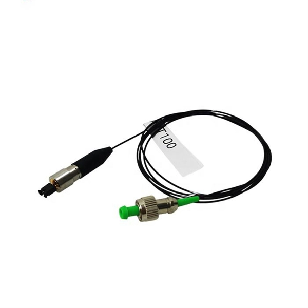
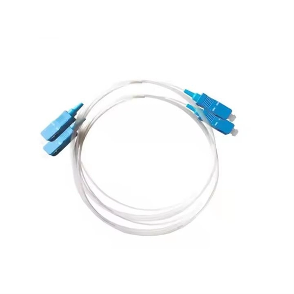
This diagram highlights media converters, switches, and cable types. Also thanks to Init7 (for the great service), r/FiberOptics and FS for providing me with what I needed to get this setup going. If you find this article useful and you are considering Init7 as your provider you can use my referral code “20700408098” to get CHF 111. - off hardware and also support me. Keeping this page as a placeholder for now. Have any questions? Talk with us directly using LiveChat. A fiber optics network diagram illustrates how high-speed data travels from an internet service provider to end users. By using light signals, fiber optics provide faster speeds and better reliability than. MS Visio has long been the default choice for drafting fiber network diagrams, and with the right stencil libraries it can be used to draw everything from backbone routes to detailed patch panel layouts. When fiber techs look for visio fiber stencils, they are usually solving a very practical. Be among the first to receive important product updates, insights and news. Fiber optic cable is used for everything from demarcation point wiring to network signal distribution to video signal extension. Often, fiber enters the structure to a centralized rack or data room where it is connected to a modem. The modem connects to a network switch which connects each remote.
[PDF]
This AutoCAD DWG file includes a complete Single Line Diagram (SLD) of a Distribution Board, showing circuit breakers, wiring connections, and load distribution for lighting, power, and mechanical systems. An electrical panel box, also known as a breaker box or a distribution board, is a crucial component of any electrical system. It serves as a central hub for distributing electricity throughout a building, ensuring that power is delivered safely and efficiently to all the required locations. And all the switching and protective devices are installed in the. A distribution box is a key part of electrical systems in buildings. Inside, you'll find parts like circuit breakers and fuses that protect the system from problems like overloads and short circuits. Today, electrical systems are essential for homes and industries. Electrical Distribution board is used for controlling of utilization of power in the end point like as lighting circuit, power circuit and other equipment like as TV, fridge and airconditioning. The incomer supply is received from distribution panel. In this board, balance load is distributed as.
[PDF]
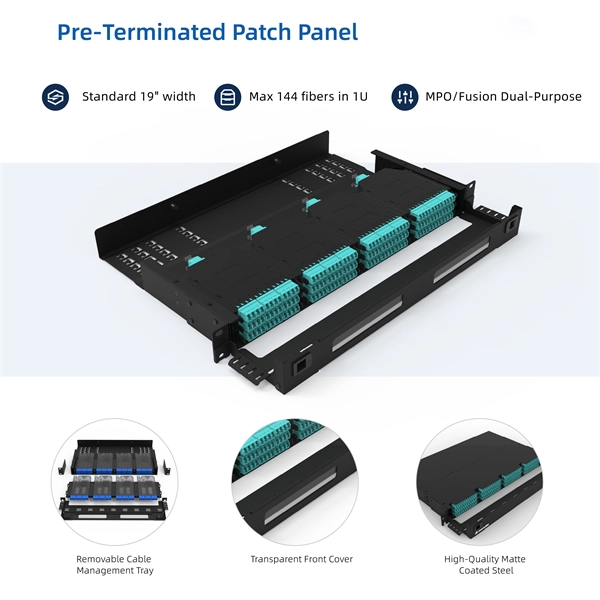
Rack Elevation or Server Rack Layout Software are simple tools to plan and document the cabling of your server cabinet. To make it even easier for you, we launched the free online Rack Planner. It helps you create a helpful rack diagram and keep your network tidy. Network cabinet cabling describes the structured connection and arrangement of all IT components in a server rack. The aim is a secure, maintainable and scalable operation of the network environment. Step-by-step guide: In this way, patch panels, switches, cable routing and documentation are. Creating a rack diagram is an important step to having sustainable good cable management in the network cabinet. Let's take a look at the essential components, selection criteria, and best practices for efficiency, order and protection of the network. Use cabinet screws to fix the network patch panel to the network cabinet. Note the wiring sequence on the patch panel when wiring, as T568A and T568B have different sequences. Wiring a server or network rack feels simple at first. Cables plug in, and devices turn on. Then problems appear. Slow speeds and tangled wires with card troubleshooting. Clean wiring prevents those issues before they start.
[PDF]

One-line diagrams and detailed network data (lines, transformers, buses). Short-circuit models, including fault current calculations under various system configurations. Protective relay settings and coordination curves. Historical. presentation of protection and control relaying. The report will identify methodology behind these practices, present issues raised by the integration of microprocessor relays and the internal logic and external communication configurations, ying. Schematic diagrams of protection relays are essential tools for power engineers in the power generation, transmission, and distribution industry. This includes AC schematics and DC schematics and diagrams that prominently feature relaying. There are other equally important types of drawings that are not the subject. Power System Protective Relays: Principles & Practices Presenter: Rasheek Rifaat, P. Eng, IEEE Life Fellow IEEE/IAS/I&CPSD Protection & Coordination WG Chair Jacobs Canada, Calgary, AB rasheek. com IEEE Southern Alberta Section PES/IAS Joint Chapter Technical Seminar - November 2016. Recognized under 2(f) and 12 (B) of UGC ACT 1956 (Affiliated to JNTUH, Hyderabad, Approved by AICTE - Accredited by NBA & NAAC – 'A' Grade - ISO 9001:2015 Certified) Maisammaguda, Dhulapally (Post Via. Kompally), Secunderabad – 500100, Telangana State, India To introduce all kinds of circuit.
[PDF]

Download a comprehensive set of Cable Tray Installation CAD Blocks in DWG format, ideal for electrical engineers, MEP designers, and industrial layout planners. This article shares simple ways to plan your cable trays and wiring. We want to help electrical engineers, technicians, and anyone working with electrical setups build safe and good systems. This collection includes installation details for ladder trays, perforated trays, solid-bottom trays, and wire mesh trays, along with. This guide provides step-by-step instructions on installing a cable tray on a wall, covering different types of cable trays, tools needed, and safety tips. The Ladder Tray features light, rugged, tubular steel construction. It is designed for. In industrial settings, electrical and instrumentation (E&I) cable trays or bridge racks play a critical role in organizing and supporting power, control, and signal cables across facilities. An effective layout ensures safety, minimizes interference, reduces maintenance time, and keeps the overall. ALL TO BE CLEANED WITH A COMMERCIALLY AVAILABLE CLEANSER PRIOR TO ALL MARKERS AFFIXED PRIOR TO INSTALLATION OF ANY CABLE. BONDING JUMPER SHALL BE INSTALLED FOR ELECTRICAL CONTINUITY ACROSS ALL DETAIL AT INTERFACES AND/OR CONDUIT BUSHINGS SHALL INSTALLED FCR ENTRY OF CABLES.
[PDF]
A typical full-size rack is 42U, which means it holds just over 6 feet (180 cm) of equipment, and a typical "half-height" rack is 18U–22U, which is around 3 feet (91 cm) high. The mounting-hole distance (as shown to the right) differs for 19-inch racks and 23-inch racks: 19-inch racks use uneven spacings (as shown to the right) while 23-inch.
[PDF]

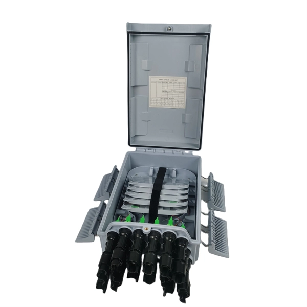
In this video, we'll walk you through the process of wiring a home distribution box with a detailed connection diagram. Whether you are an electrical contractor or a construction brigade, knowing how to properly and safely install distribution boxes is the basis of ensuring the safe operation of the entire system. This article details the process of installing them, which helps you comprehend distribution boxes. In modern electrical systems, cable distribution boxes (also known as electrical distribution boxes or distribution boxes) play a crucial role as the key hub for managing, distributing, and protecting circuits. Covers wiring, placement, standards, and expert tips for a compliant setup. A distribution box is the heart of any electrical system. It takes the incoming power and safely distributes it to different circuits throughout your building. What is Distribution Board? Distribution board. Mounting new electrical boxes is a simple process, but the job does require careful planning. You don't have to create a to-scale.
[PDF]
Standard rack installation: $500 to $2,000 per rack. Equipment Costs. The costs associated with rack and stack solutions can vary significantly depending on several factors. These include the size of the installation, the complexity of the equipment, labor costs, and infrastructure requirements. Size of the Data Center The scale of the data center plays a large. Check each product page for other buying options. VEVOR 9U Wall Mount Network Server Cabinet, 15. 5" Deep, Server Rack Cabinet Enclosure, 200 lbs Max. Ground-Mounted Load Capacity, with Locking Glass Door Side Panels, for IT Equipment, A/V Devices Need help?. 9U Wall Mount Network Server Cabinet, 15. Did You Find It?. The 9U rack is an ideal choice for smaller setups, that provides enough space for easy access and airflow. 9U 18" Depth Wall Mount 19" Enclosure SR. Transit within 4-6 business days 19" Wall Mount Server Rack Cabinet 9U (24"w x18"d x20"h) (. Transit. This SmartRack® 9U rack enclosure is designed for home and office network wiring closets, retail locations, classrooms, back offices and other areas with limited floor space where you need equipment to be secure, organized and out of the way. Constructed from heavy-duty steel with a durable black. Learn why IT Pros trust StarTech. com for performance connectivity accessories.
[PDF]
Room 641A is located in the SBC Communications building at 611 Folsom Street, San Francisco, three floors of which were occupied by AT&T before SBC purchased AT&T. The room was referred to in internal AT&T documents as the SG3 [Study Group 3] Secure Room. The room measures about 24 by 48 feet (7.3 by 14.6 m) and contains several racks of equipment, including a Narus ST. Overview Room 641A is a telecommunication interception facility operated by for the U.S., as part of an. The (EFF) filed a class-action lawsuit,, against the company on January 31, 2006, accusing the telecommunication company of violating the law and the privacy of its customers. • Page 17: Basic diagram of how the alleged wiretapping was accomplished. From court filings. • Page 9: More complicated diagram of how it allegedly worked. From EFF court filings. .
[PDF]
Data Center Resources specializes in mission critical environments. Our full line of products and services effectively power, cool and monitor critical systems. DCR is a unique hybrid of a manufacturer and distributor. Our proprietary products such as the Cool Shield aisle containment system and. Accelevation containment systems are customized for the unique data hall environment and are designed to separate cold supply airflow from hot air coming out of equipment exhaust, while maintaining ease of access to critical equipment. Properly configured, containment systems can reduce energy. Cold aisle containment creates an enclosed corridor in front of server cabinets, ensuring that the coldest air goes directly into equipment intakes. By isolating the cold aisle, containment reduces unintended mixing of cold supply air with hot exhaust air, maintaining uniform, predictable. An aisle containment system is a simple way to improve cooling efficiency in hot aisle/cold aisle rack configurations. Cool Shield™ containment offers state-of-the-art hot and cold aisle containment solutions designed to maximize data center efficiency while significantly reducing. Aisle containment top roof ceilings, walls and end of row doors are designed to help maintain optimal operating temperature in server rooms and data centers in order to lower data center energy demands and save on energy costs. AZE offers a wide range of partial and total containment solutions that.
[PDF]
Entrust your server hardware to the best hands and reap the benefits of our outstanding infrastructure. Experience unparalleled affordability and scalability for server housing in Albania and Germany. PORTABLE LABEL MAKER: Compact and lightweight for portability, making it easy to label just about anything, anywhere PRINTS CUSTOM LABELS: Choose from 5 font sizes, 7 print styles and 8 box styles PREVIEW TEXT EFFECTS: See font effects on screen. Please note that we are currently only able to guarantee rack availability in the Tirana, AL. Leksus Stand Alone Rack Network 42U 600x600 LKS426060 Specifications: Glass front door Sheet steel rear door Detachable side panels Bottom and roof panel with ventilation holes 4 x 19 inch profiles with height indications Doors can be. Specifications: Glass front door Sheet steel rear door. Your Smartarget Whatsapp - Contact Us is visible on the homepage only + Smartarget branding. LOGILINK 19" CABLE ORGANIZER 1U. BLACK NP0048 LANDE CABINET WALL MOUNTED. 9U 19 EUROBOX W=540MM D=600MM. 7U. CloudyHost is the market leader for domains, hosting, cloud, dedicated servers, e-security, and eCommerce. 8 years alongside our customers! The company offers managed hosting and server configuration services, emphasizing the importance of professional server management for enhanced performance and. IT networks | Racks and cabinets | !.
[PDF]