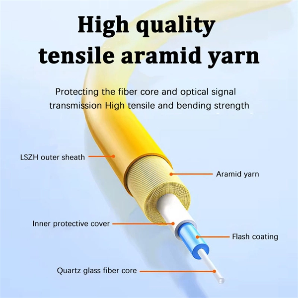
Can two switches with fiber ports be directly connected through fiber ports? The answer is yes. The connection between two or more Ethernet switches in a certain way (Uplink port, etc. ) is. If you have multiple Ethernet switches that need to be connected over long distances, fiber is obviously a preferred choice. Moreover, when it comes to bandwidth, no currently available technology is better than single-mode fiber. ) is called the cascade. I need to connect a single 3750G - 48 ports switch to a single 2960 - 48 ports switch and it needs to be through a fiber. So, PCs connected to one switch would reach the PCs from the other switch. Well, I. Other than entry level network switches, most of today's network switches include one or more GiBC (Gigabit Converter) or SFP (Small Form-factor Pluggable) slots. SFP modules insert into these slots and and require two strands of fiber, typically duplex Using multi mode fiber (for runs under 1000. Fiber optic cabling is increasingly used to connect network switches and other datacom equipment, especially in long-distance and mission-critical applications. Fiber provides: Increased internet signal bandwidth. Most modern fiber-enabled network switches require an SFP transceiver module. I have an issue when connecting two switches with fiber. The switches connect as expected when in the same room and connected using 1m or 3m patch cables. This is where it gets strange.
[PDF]
The QSFP28 transceiver provides 100GBase-BX throughput up to 20km over single-mode fiber (SMF) using a wavelength of 1310nmTx/1280nmRx via an LC connector. This bidirectional unit must be used with another transceiver or network appliance of complimenting wavelengths. Whether it's building a network or upgrading an existing network, the Cisco® QSFP-100G-B20U4-I and QSFP-100G-B20D4-I transceivers provide 100G connectivity for platforms at up to 20km on single SMF (Single Mode Fiber). This. The QSFP-100G modules are our latest generation of 100G transceiver modules solution based on a QSFP form factor. Table 1 describes the Cisco QSFP-100G portfolio. Cisco QSFP-100G Portfolio The Cisco 100GBASE-SR4-S QSFP Module supports link lengths of up to 70m. To meet the demand for long-distance transmission in scenarios where optical fiber resources are scarce in edge access networks, Walsun has launched the 100G QSFP28 ZR4 BIDI product, and will demonstrate 100G 80km single-fiber bidirectional service transmission at OFC 2024. 66nm-RX) via an LC. NEC's 100G QSFP28 BiDi optical transceiver enables the transmission and reception of 100Gb/s high-speed data over a single optical fiber. By enabling bidirectional transmission over a single fiber, this module enhances fiber utilization efficiency and can reduce fiber costs. ZR4 BiDi, using four.
[PDF]
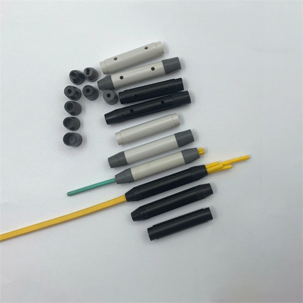
Instead of fusing one fiber at a time, mass fusion splicing can fuse up to all 12 fibers in one ribbon at once. Many of today's cables with high fiber count involve subunits of 12 fibers each that can be quickly ribbonized. Fiber optic joints or terminations are made two ways: 1) splices which create a permanent joint between the two fibers or 2) connectors that mate two fibers to create a temporary joint and/or connect the fiber to a piece of network gear. Either joining method must have three primary characteristics. Fiber optic splicing is the process of seamlessly joining two single Splicing has a lower optical loss and back-reflection than other terminations, making it the ideal choice for maintaining signal integrity and reliability in fiber optic networks. There are numerous use cases for fiber optic splicing. Through splicing, fiber optic technicians can extend the length of the fiber to make it long enough for use in a required cable run. As. To begin, the standard definition of splicing in optical fiber is joining two fiber optic cables together. The other, more common, method of joining fibers is called termination or connectorization. Splicing is most commonly used in the field but has application in cable assembly houses.
[PDF]
To connect an optical cable to an SFP module, use the appropriate patch cord (e., LC-LC, SC-LC, etc. The patch cord must match the fibre type – single-mode or multi-mode. Once connected, verify that the port activity indicator is on and run diagnostic commands to check the. Small Form-factor Pluggable modules (SFP module) are the workhorses of modern network connectivity, enabling flexible fiber optic or copper links between switches, routers, firewalls, and servers. Whether you're upgrading bandwidth, replacing a faulty unit, or reconfiguring your topology, knowing. Connecting your fiber optic cable to an SFP (Small Form-factor Pluggable) module can seem daunting if you're unfamiliar with networking hardware. However, with a bit of guidance, the process is straightforward. Remove the dust caps from the SFP module and the fiber optic cable. Today, we will discuss the best methods to connect SFP to fiber optic patch cables. To connect a fiber optic cable to SFP optical module, first ensure the SFP is fully inserted into the network port until it "clicks", then remove the dust caps from both the SFP and the LC fiber optic connector. Laser Compliance The fiber-optic SFP+ / SFP28 modules contain a laser that is classified as a “Class 1 Laser Product” in accordance with US FDA regulations and the IEC 60825-1. The product does not emit hazardous laser radiation. The module is fully seated when you hear a click. (SFP+ and SFP28.
[PDF]
The evolution of fiber optic transmission systems has seen advancements such as dense wavelength division multiplexing (DWDM), coherent transmission technology, modulation format improvements, increased transmission speeds (e., 100 Gbps, 400 Gbps), and the adoption of. The winding journey of fiber optics is a story of persistent progress. From Daniel Colladon's 1841 demonstration of light guidance in water to recent advances empowering multi-terabit infrastructure, researchers continuously pushed the boundaries of optical communication. Early steps like total. Created by the Fiber Optic Association as an educational project to help document the history of the development of fiber optics for communications. Dates, of course, are often approximate, as putting a firm date on the introduction of a new technology is often impossible! the most important. Discover the latest developments in fiber-optic communications with the newest edition of this leading textbook In the newly revised fifth edition of Fiber-Optic Communication Systems, accomplished researcher and author, Dr. Agrawal, delivers brand-new updates and developments in the. The evolution of fiber optic networks has been a steady and methodical journey of technological advancements that have revolutionized the way we communicate and transfer data. From its inception as a theoretical concept in the 1960s, fiber optics has undergone significant developments, resulting in.
[PDF]
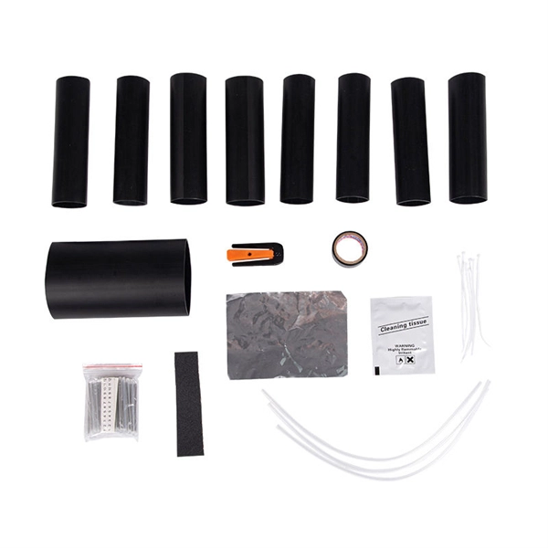
With a variety of kit options available, you can choose between the easy-to-use Quick Clean™ Cleaners, the convenient cleaning cube/card, and the best optic solvent pen to clean both patch cords and fiber.
[PDF]
This video makes connecting your fiber optic cable to your router a breeze! We'll guide you through the entire process step-by-step, ensuring a smooth and hassle-free experience. Our Experts are helping user's, who are facing issues with their tech gadgets like. In this guide, we'll walk you through how to connect a fiber optic cable to a router safely and efficiently. Why Use Fiber Optic Internet? Before diving into the setup, let's quickly recap why fiber optics are worth the effort: Lightning-fast speeds (up to 1 Gbps or higher). This comprehensive guide combines industry standards with field-tested practices to ensure you achieve a rock-solid. Setting up a fiber internet connection requires understanding key hardware components and following a specific connection sequence to establish your home network. This guide details the necessary physical and digital steps to connect your fiber line and activate your internet service. If you. Connecting a fiber optic cable to a router might seem daunting at first, but with the right tools and a bit of patience, it's a straightforward process. Here's a step-by-step guide to help you through it. Check compatibility: Before you begin, make sure your router supports fiber optic connection. Not all routers can connect directly to a fiber cable, so it is important to verify this information before continuing.
[PDF]
The os3150 and os3155 are rugged, spot-weldable optical strain gage based on fiber Bragg grating (FBG) technology, with optional integrated temperature compensation. The os3100 Optical Strain Gage is designed to make fiber handling easy and sensor installation fast and repeatable. Its stainless steel carrier holds the FBG in tension, using no epoxy. SCAIME has developed a complete range of fibre-optic strain gauges for monitoring complex structures. Since there are no. What are Optical Strain Sensors? Optical strain sensors (or strain gauges) are sensors for compressive and/or tensile mechanical strain (deformation) which are based on optical technology — in most cases, on fiber optics. They can be based on different operation principles as explained in the. Fiber Bragg grating strain gages can be delivered pre-laminated for measuring strain on stiff surfaces. They are suitable for being fixed easily onto the measurement object, like concrete beams, or rocks. These sensors possess great sensitivity and reliability, which explains their growing popularity across various engineering and monitoring applications. The fiber optic strain gauge is directly attached onto the.
[PDF]
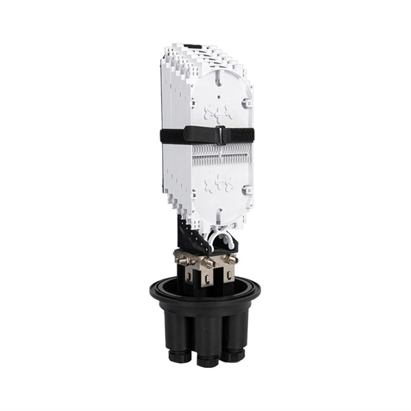
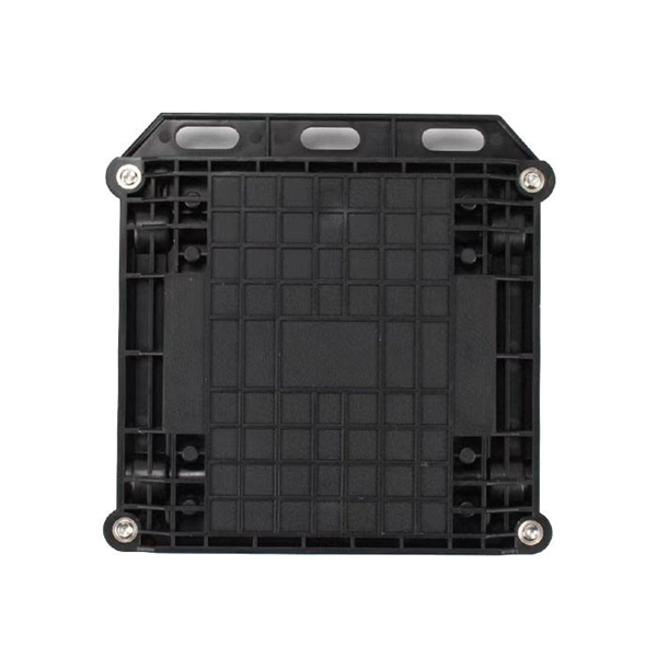
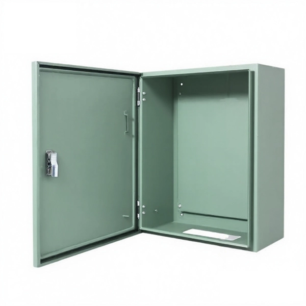
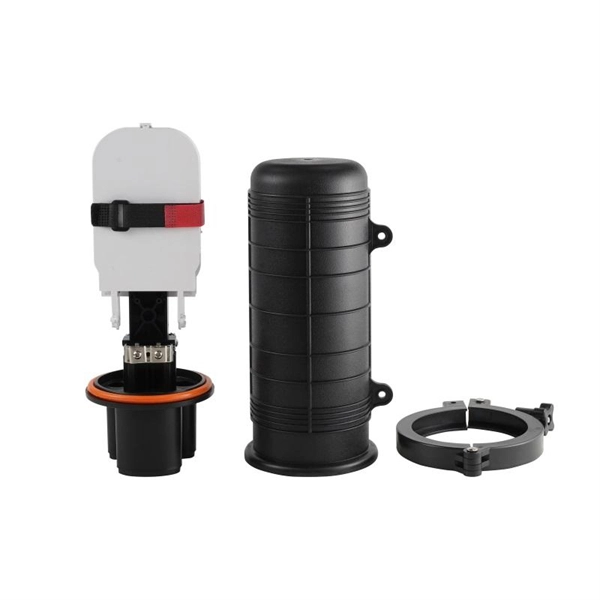
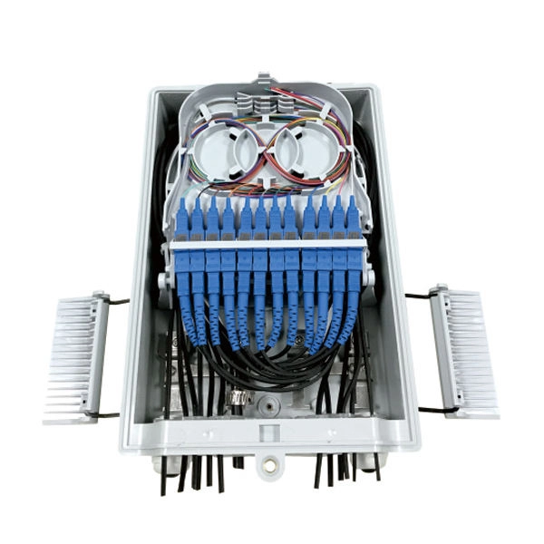
The fiber optic distribution box accomodates up to 6 core fibers and supports outdoor applications within FTTH network system. The type of installation for 6 core distribution box is wall-mounted. The entry size of the drop cable is perfectly designed to accommodate 2x3 millimeters. Serves as a critical termination and distribution point in FTTH networks, offering mechanical protection for fiber optic connections. Ideal for both indoor (residential buildings, offices) and outdoor (exterior walls, utility areas) environments, ensuring durability in diverse conditions. The enclosure supports fiber splicing, splitting, and distribution within a single compact unit, ensuring organized cable routing and secure fiber. [Flexible Flip Board Design] The rotatable flip board allows for up to 180 degrees of flipping, enabling easy angle adjustments during use. [Robust Material] Constructed with abs material, this fiber distribution box offers excellent toughness, strength, wear, and impact. [Minimal Optical Loss]. FBR-11606 Fiber-Optic Distribution Box, 6-Core is a high quality product by Bud Industries used for electronic enclosure applications. It's easy to splice, split and manage the fiber in the box. FDB can provide solid protection and easy maintenance for FTTx network construction.
[PDF]

Optical splitters enable a signal on an optical fiber to be distributed among two or more fibers. Since fiber splitters contain no electronics nor require power, they are an integral component and widely used in most fiber-optic networks. A fiber optic splitter is a passive optical component that divides a single incoming optical signal into two or more outgoing signals, or combines multiple incoming signals into one. Unlike active devices (which require power), splitters operate without electricity, relying solely on the physics of. Optical cables, also known as fiber optic cables, consist of thin strands of glass or plastic fibers surrounded by a protective casing. These fibers transmit data as light signals, which are converted into electrical signals at the receiving end. The benefits of optical cables are numerous. A fiber-optic splitter, also known as a beam splitter, is based on a quartz substrate of an integrated waveguide optical power distribution device, similar to a coaxial cable transmission system. Its primary role is in Passive Optical Networks (PON), which are the foundation of. A fiber broadband provider typically determines and overall split ratio for the network, such as 1x32 or 1x64, and uses combinations of splitters to meet that ratio with each PON port. 1x32 splits were common in North America for G-PON architectures. As XGS-PON continues to be adopted, some service.
[PDF]
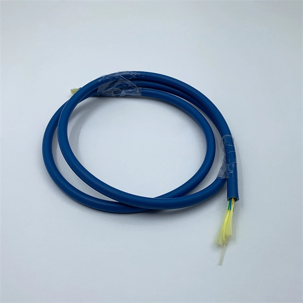
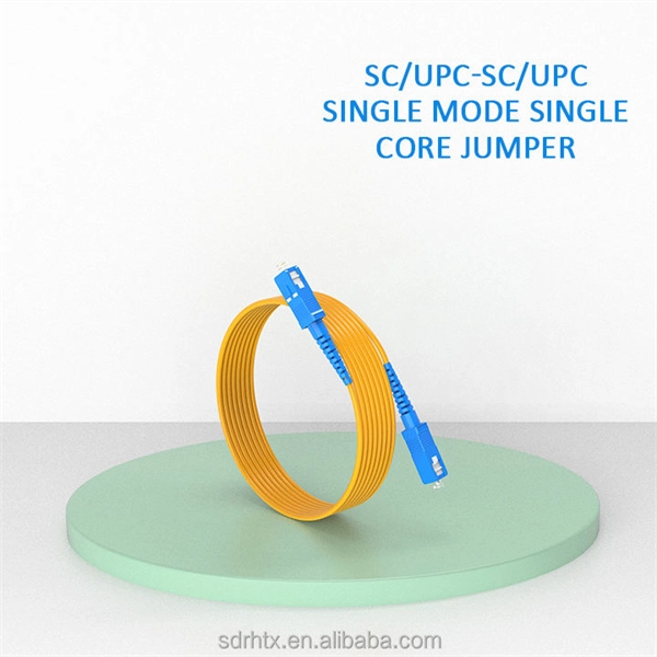
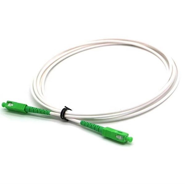
The answer has to do with the connector endface polish, or the angle of connection, and the good news is connectors also follow industry-standard color codes. Fiber connectors are often used as the terminations of optical fiber cables to provide non-permanent connections between fiber-coupled devices (a kind of removable fiber joints). They are used in a similar manner as electrical connectors. This allows for quickly connecting and disconnecting of fiber optic cables without splicing. The connector features a ferrule, the connector end piece that holds and secures the fiber and aligns it for light. The fiber connector is called a fiber optic or optical fiber connector. A link's transmit signal (Tx) must match its corresponding receiver (Rx) at the other end. Although it may seem obvious, fiber optic polarity is a frequent source of confusion and. Fiber optic patch cables consist of the connectors on the ends of the fiber cable. The options on these cables dictate the fiber type, connector type, polarity, and polish type. The fiber types are SMF (Single-mode fiber) and MMF (multimode fiber). The most common connector types are LC, SC. The fiber connector types, sometimes referred to as terminations, link fiber optic cables together through terminals, switches, adapters, and patch panels, by bridging the gap between their internal glass fibers that transmit the data down the length of the cable. The ferrule, a cylindrical.
[PDF]
Total number of cores = Number of branches × Number of cores per branch If there are no branches, the number of branches equals one. For example, an MTP®-8 trunk cable with four branches and eight cores per branch has a total of 32 cores (4 × 8 = 32). For example, if you have three optical fiber access switches, you need to have three cores. (actually use a four core optical cable) This is because apart from one-core optical fiber, there are basically no optical cables with an odd number of cores, such as three-core, five-core, etc. It is worth. Fiber cores are the heart of fiber optic cables, transmitting light signals that carry data. Made from either high-quality glass or plastic, the core plays a critical role in determining the cable's performance. The total number of cores for a 1pc fiber patch cable is calculated as the number of. One key factor is the number of cores, which impacts how much data you can transmit. Single-mode: A. Common fiber cores include 1 core, 2 cores, 6 cores, 8 cores, etc., and there are many types. This article will focus on the number of fiber cores, introducing their respective characteristics and usage scenarios. Of course, this is a general situation, and it can be considered as follows: 1.
[PDF]
Our list for Fiber optic products suppliers in Venezuela is one of the most comprehensive in the industry. As of May, 2026, we have compiled data on 20 verified listings. Zulia makes up approximately 40% of all Fiber optic products suppliers in. Optromix R&D team, established in 2004, has an extensive experience in the development of fiber optic products and solutions, based on the advanced research work and patents of internationally recognized scientists. Manufacturer Based in Newton, MA. When producing fiber. We offer a full range of FRP products including gratings, railings, ladders, stairs, plates and work platforms. In addition to our standard FRP stair solutions and structural products, we provide fiberglass reinforced plastic products with resin formulations engineered for specific corrosion. There are 23 Fiber Optic Products Suppliers in Venezuela as of October 8, 2024; which is an 0. 00% increase from 2023. Of these locations, 21 Fiber Optic Products Suppliers which is 91.
[PDF]
Prices typically range from about $0. 50 per foot for fiber optic cable and basic installation, depending on indoor vs outdoor routing, distance, and terrain. Commercial building installations with 100-200 network drops generally range from $15,000 to $30,000. Single-mode fiber costs less per foot than multimode fiber, but it requires more. Buyers typically see a wide range in fiber cost per foot depending on cable type, installation method, and terrain. The main cost drivers include cable type (single-mode vs multimode), whether the run is indoors or outdoors, trenching or direct burial requirements, and labor time. This guide presents cost ranges in USD and highlights how per-foot pricing translates to total project costs for typical. The Fiber Broadband Association has partnered with Cartesian to research the cost of deploying fiber and provide insight on how these costs are evolving over time. In preparing this second edition of the Fiber Deployment Cost report, Cartesian gathered inputs from a wide variety of firms building. 1) Proofing and Placement - Per foot pricing for proofing and placement of approximately 1,856,332 ft (351. 864F Prysmian non-armored ribbon cable (24 Fibers per ribbon) into existing empty. conduit (price includes the provision of redline documentation, fiber cable. Buyers typically pay for the cable itself, termination hardware, and professional installation. The following guide outlines typical costs, with practical ranges in USD.
[PDF]
Main Purpose: 6-core fiber optic distribution box, widely used in FTTH project, easy to construct and provide good protective operation. Fiber optic terminal junction boxs are designed to provide a safe and organized solution for managing fiber optic cables in indoor and outdoor. FBR-11606 Fiber-Optic Distribution Box, 6-Core is a high quality product by Bud Industries used for electronic enclosure applications. The HTB8009 6 Ports FTTH Termination Box is a compact, multi-functional distribution enclosure specially designed for final fiber termination at the user end in fiber-to-the-home (FTTH) applications. Built from UV-resistant ABS material, the box combines durability with a sleek form factor, making. The structure of the product is compact, which can meet the needs of various optical cable installation, convenient construction and reliable sealing. Water-proof design with IP65 portection level. Integrated with splice cassette and cable management system. The type of installation for 6 core distribution box is wall-mounted. The entry size of the. Max. Capacity Gcabling is a leading fiber box manufacturer & supplier. We can manufacture and supply a wide range of fiber termination boxes with 20+ years of experience.
[PDF]