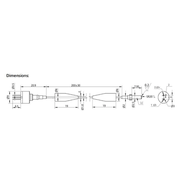
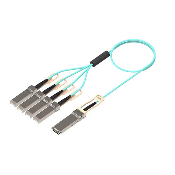
Active Optical Cables simplify high-speed networking by embedding tiny optical transceivers directly into the cable ends. Inside one compact assembly, electrical signals convert to light pulses, travel through the fiber core, then reconvert to electrical form—eliminating separate. When traditional copper cables hit their physical limits, Active Optical Cables (AOCs) emerge as the superior solution for demanding, high-bandwidth applications. These change electrical signals into optical signals and back. This gives. Active optical cable (AOC) is a high-performance communication cable used for short-range multi-lane communication and interconnected applications. Unlike traditional fiber-optic cables, which require external transceivers to send and receive signals, AOC cable have the necessary transceivers integrated. Thanks to the intricate design of Active Optical Cables, which allows for flexibility and gives an extra advantage of unmatched stability. Alt Text: A Group of AOC Cables with Different Connectors In the following paragraphs, you will be broadly enlightened about every aspect of the cutting-edge. Active Optical Cables (AOCs) are an innovative type of data transmission technology that has come forth to fill the gap between the old copper cables and the ever-advancing fiber optics. Unlike the traditional methods, AOCs are explicitly structured to provide long-distance connecting devices to.
[PDF]
When discussing industrial electrical cabling, the significance of cable trays becomes evident. A specific arrangement must be implemented for larger cables to prevent entanglement, ensuring easy comprehension during maintenance and proper upkeep. Tired of messy wires causing headaches? Brilltech Engineers Pvt. brings the Cable Trays in Jamaica just for you! We, one of the well-known Cable Trays Manufacturers in Jamaica, offer top-notch trays that keep your electrical system organized and protected. Our custom-based products are able to match up your distinct needs. Our products are known for their sustainable performance and all the other features that it. In an effort to obtain more realistic assessment data the assessment and withstand demonstrators have been combined into a common two-piece unit. Cablofil cable tray is the revolutionary system constructed of precision-engineered, high-quality, welded steel wire. The Cablofil system includes everything to make installation effortless and it adapts easily as your cable management needs grow and c hange. The FAS support system is exclusively. Make a Payment We provide High Quality Products & excellent customer service to our clients. + (876) 618-6790. us-trations without notice.
[PDF]
It is designed for real-time monitoring of power distribution lines, performing fault detection, fault waveform recording, fault section pinpointing, risk alerting, and power quality analysis. The Power Distribution Overhead Line Monitoring System comprises sensors, concentrators, the data analytic platform, and AI algorithm modules. This paper presents a SCADA-based real-time fault detection. ABB has a wide portfolio of smart power distribution solutions, that can be integrated into secondary switchgears, as well as complete compact secondary substations (CSS) - delivered as turnkey solutions. The remote monitoring and control REC615 (1) is an integrated protection and control relay in. This paper presents a method to detect and classify the high impedance fault that occur in the medium voltage (MV) distribution network using discrete wavelet transform (DWT) and adaptive neuro-fuzzy inference system (ANFIS). This paper designs a monitoring system that collects the internal status data of the power distribution cabinet. The vacuum circuit breaker is equipped with advanced arc extinguishing chambers and contact systems to ensure rapid breaking of fault currents, and is coordinated with current and voltage transformers and various protective relays to achieve comprehensive system monitoring and safety protection.
[PDF]
It transforms high volumes of electrical signals into optical signals for transmission over fiber cables, or reverses the process at the receiving end. Think of it like a Type-C to USB adapter in everyday tech—its core function is seamless conversion between electrical and optical. An optical transceiver, a crucial device utilized in optical communication, is an optoelectronic element, allowing the interconversion of optical and electrical signals during the information transmission. It generally has the components for transmission, reception, laser chips, photodetctor chip. A fiber optic transceiver (also called an optical transceiver) is a compact module that both transmits and receives data signals through optical fibers. It serves a dual purpose — transmitting electrical signals as light pulses and receiving light pulses to convert them back into electrical form. They perform key functions: Electrical to Optical Conversion: The transmitter. This page explains the basics of optical transceivers and their function within a fiber optic network. The term “Transceiver” simply refers to any device that combines both transmitter and receiver functionalities in a single package. The device that transmits and receives RF signals is known as an. In the era of 5G, AI, and high-speed data centers, optical modules serve as the core bridge for converting electrical signals to optical signals (and vice versa), enabling fast, reliable data transmission across networks.
[PDF]
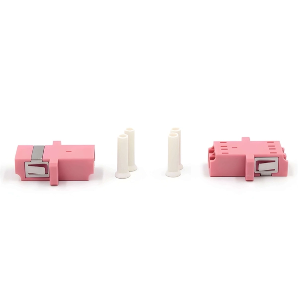
At a fundamental level, a fiber optic coupler is a device that distributes or combines optical signals (light) between two or more optical fibers. In simple terms, they serve as the 'traffic managers' of the light that carries information within the fiber optic network. A fiber optic pigtail is actually the end of a fiber optic cable with fiber optic connectors on both sides of the cable only, leaving no connectors on the other side so that the connector side can come from the device and the other side can be fused together with the fibers of the optical cable. The working principle of. A coupler can be used as a splitter to couple out some portion of the light circulating in the resonator of fiber laser, for example. Directional 2 × 2 couplers (see Figure 1) are usually used for such purposes. It functions by dividing a single incoming light path into multiple outgoing paths, or by combining light from several input paths into a single output fiber. This capability is fundamental. Couplers are mainly used for fiber optic wiring, fiber optic equipment connection and other occasions. Inspirational to provide you with the highest quality products. Adapter insertion loss is typically 0.
[PDF]
Live (L) Wire Connection: In a distribution box setup, the incoming live wire (also known as phase or hot wire, denoted as L or Line) connects to the line terminal of the circuit breaker. This serves as the primary source of electrical energy from the mains supply. Correct wiring methods for circuit breakers within distribution boxes are fundamental to ensuring electrical safety and compliance with established codes. The distinction between 1P and 2P circuit breakers plays a pivotal role in determining the appropriate protection level for various circuits. And all the switching and protective devices are installed in the distribution box. Single Phase Distribution Box generally consists of Double Pole MCBs, Single Pole MCBs, and RCCBs. The wire neutral is the return line in an electrical system that brings current from the electrical equipment back to the transformer or distribution box, completing the loop closure of the current. Figure 2-3 What wire is neutral? What does the neutral wire do? Although the neutral wire is usually. Live wires carry the power from the source to a switch or appliance. These may be light switches, electrical outlets, or junction boxes for light fixtures. The live wire is always under voltage, meaning it carries the. The main service panel, also known as the breaker box, is the central distribution point for the home's electrical system.
[PDF]
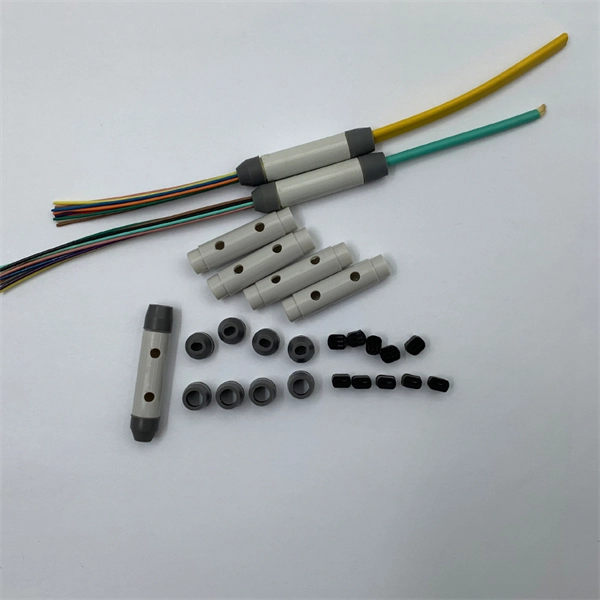
A pigtail connector is a short length of wire with a factory-terminated connector on one end and bare, exposed wires on the other. It serves as a bridge, allowing technicians to repair specific connection points without disturbing the rest of the system. These connectors can be a big help when you need to connect two wires, repair damage, or extend a. This is where the pigtail connector becomes an essential solution. What Is a Pigtail Connector? Types and Applications A pigtail connector is a short cable with a connector on one. Whether you're replacing an outlet or adding a new fixture, knowing when and why to use a pigtail can save you time and prevent potential hazards. It's a small detail with a big impact on your electrical setup. Let's learn more from this blog! What Is A Pigtail In Electrical Wiring? A pigtail in. Fiber pigtails are simple in appearance, yet essential in function. They are the bridge between fiber optic cables in the field and the equipment or patch panels that manage them. By combining factory-installed connectors with spliced bare fiber, pigtails ensure that network installers can create. A pigtail connector is a short, pre-terminated length of cable with one end connected to a connector and the other end left open or spliced into another assembly. It allows easy integration of connectors into systems where direct termination is difficult. Pigtails are widely used in RF, fiber.
[PDF]
Its primary role is to carry large current loads and connect multiple circuits together. Think of a bus bar as the main highway for electrical current—allowing it to flow between components with minimal resistance and voltage drop. In electric power distribution, a busbar (also bus bar) is a metallic strip or bar, typically housed inside switchgear, panel boards, and busway enclosures for local high current power distribution, transmission, or switching substations. Think. The electrical panel, often called the breaker box, functions as the central distribution point for all electricity entering a home. While circuit breakers are the visible safety components, the internal system that routes and distributes the power is built around the bus bar. It acts as a central hub, connecting multiple circuits and ensuring current flows efficiently. A busbar's main function is to conduct and distribute large electrical currents from one source to multiple circuits within an enclosure, acting as a central, high-capacity connection point. My insights show that understanding the practical function is key. As I've seen in the field, the textbook.
[PDF]
Your breaker box wiring includes three main wire types: black hot wires carry electricity to outlets, white neutral wires return unused power, and green ground wires prevent electrocution. The goal is to distribute circuits evenly across both L1 and L2 to keep things balanced and prevent any traydropping electrical mishaps! Now, what happens when you need more power than a single 120V line can deliver? That's where splitphase power comes in. When a circuit connects L1 to L2 (instead. A distribution board or distribution box is where the main power supply is distributed to multiple loads. And all the switching and protective devices are installed in the distribution box. Single Phase Distribution Box generally consists of Double Pole MCBs, Single Pole MCBs, and RCCBs. Wiring – Includes live, neutral, and earth wires for power distribution. Circuit Breakers – Protect the system from overloads and short circuits. Electrical switchboards can have different setups based on their. The neutral wire carries the electricity back to the power source. It completes the circuit by directing the current to a ground or busbar, normally located at the electrical panel. Once the power is “used” at the demand point, it carries it back to the panel. Note: Read my Article on 5KW Solar System Installation, you can do it yourself. Its a complete Guide. It is typically colored black, red, or another color designated for live wires.
[PDF]
A PLC splitter is a passive optical device that divides one incoming optical signal from an input fiber into multiple output signals across several output fibers. PLC splitters utilize a planar lightwave circuit chip made of silica glass waveguides to distribute the optical power. PLC optical splitters (planar waveguide optical splitter) is a key component in optical fiber communication networks and is widely used in optical fiber distribution systems such as FTTH (fiber to the home) and PON (passive optical network). This passive yet sophisticated device utilizes integrated optics technology to split a single input signal into multiple. PLC splitter, also called Planar Waveguide Circuit splitter, is a device used to divide one or two light beams into multiple light beams uniformly or combine multiple light beams to one or two light beams. This helps share signals in fiber optic networks. Pick the split ratio that matches what you need. Lower ratios work for fewer users. Choose the connector type like SC, LC, or FC.
[PDF]
Use high-quality photoelectric integrated modules to provide good optical and electrical characteristics Ensure reliable data transmission and long working life Support full-duplex or half-duplex mode with auto-negotiation capability The network port supports automatic. Use high-quality photoelectric integrated modules to provide good optical and electrical characteristics Ensure reliable data transmission and long working life Support full-duplex or half-duplex mode with auto-negotiation capability The network port supports automatic. This comprehensive guide breaks down the internal structure, core components (TOSA, ROSA, lasers), and operational mechanisms of SFP optical modules, enriched with technical insights and real-world applications. As a leading provider of optical communication solutions, Weunion integrates these. The Cisco ® family of QSFP-DD modules provide the industry's highest bandwidth density while leveraging the backward compatibility to lower-speed QSFP pluggable modules and cables. The Cisco 400GBASE Quad Small Form-Factor Pluggable Double Density (QSFP-DD) portfolio offers customers a wide variety. On an optical network, a sender needs to convert electrical signals into optical signals before sending them to a receiver, and the receiver needs to convert received optical signals into electrical signals. Despite the rapid adoption of 10G and higher-speed.
[PDF]
This guide highlights five top-rated options, detailing their tech specs, durability, and ease of use. Each entry provides a quick overview so you can compare sizing, IP ratings, and mounting features before choosing. Limitations of “Dumb” Waterproof Boxes + “Smart” Indoor Switches: Many attempt to achieve outdoor automation by placing an indoor smart switch inside a generic waterproof outdoor electrical box. This creates several problems: —Signal Degradation: The metal or thick plastic of the outdoor box can. We specialize in creating custom NEMA enclosures tailored to your exact needs. Browse our durable lineup of outdoor electrical enclosures designed to protect sensitive components from rain, dust, UV exposure, and harsh environmental conditions. Built for rugged reliability, these enclosures are. Exterior electrical boxes are weatherproof enclosures that protect outdoor electrical connections from moisture, dust, and impact damage. Here's what you need to know: Key Features to Look For: Top Applications: Whether you're adding a new outdoor outlet for holiday lights or upgrading an existing. Discover the 5 best outdoor electrical junction boxes for weatherproof protection. Compare features, materials, and ratings to ensure safe, code-compliant installations. When you're running electrical wiring outdoors, proper protection isn't optional—it's essential for safety and code compliance. Each option balances.
[PDF]
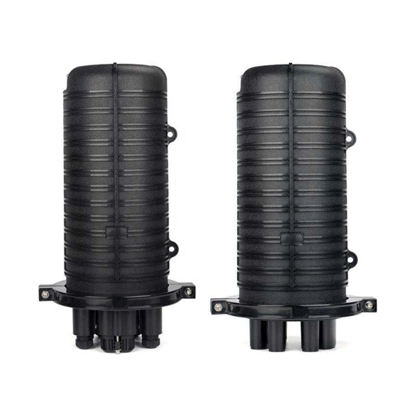
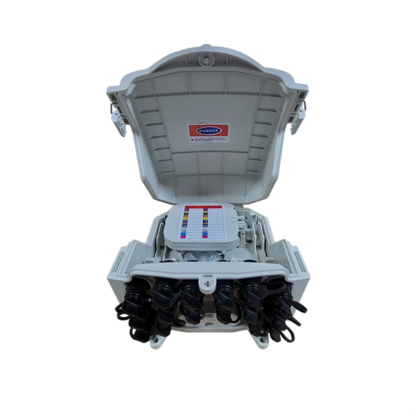
A distribution box serves as a central point for managing and distributing fiber optic cables. This device ensures reliable and efficient connectivity between various network components. The distribution box provides a secure environment for splicing, terminating, and organizing. Optical cable distribution boxes are essential components in modern telecommunications infrastructure. As digital connectivity demands grow, these boxes are becoming more versatile and widespread. They function as junction points that manage, protect, terminate, and distribute fiber optic cables, ensuring efficient data transmission between different. The Fiber Optic Distribution Box plays a critical role in the aggregation, branching and protection of fiber optics, particularly in FTTH (fiber-to-the-home), LANs and MANs. It begins with an introduction to fiber optic technology and the pivotal role of distribution boxes.
[PDF]
Insert the hose barb into the hose and measure the O. 025" to that measurement. Use that figure for the I. D (inside diameter) of the ferrule. Blasch's shape making capability allows us to engineer round and hex ferrules to meet your boiler specifications and application. Ferrules can be made in a variety of high purity thermal shock resistant ceramic materials, such as 99% alumina, as well as metallic alloys. For more information or to. We provide high precision custom and special size zirconia ferrules, with OD sizes ranging from. The ID sizes range from 80 microns to 1500 microns, in any length from 2. All custom ferrules are precision made with tightest tolerances to meet your unique application. Image Industries supplies ceramic ferrules with all of the drawn arc weld studs we sell. The types of ceramic ferrules that Image Industries supplies. r's quality is the zirconia ceramic ferrule. The degree of ferrule concentricity and the tightness of the ferrule's inner diameter (ID) are key factors that influence the ex ent of lateral misalignment during connection. of the hose barb being used and make sure the hole size. Furthermore, it shields the operator from both arc and spatter. The ceramic ferrule is used for one weld only and is removed once the molten metal has solidified. Solid ceramic ferrules with high precision size and low water absorption rate, can significant improve the weld result.
[PDF]
The key objective of reflow soldering is to ensure consistent, high-quality solder joints while minimizing thermal damage to components. It involves precisely controlled heating and cooling cycles that melt and solidify solder paste in a repeatable manner. Reflow soldering is a core process in modern surface mount technology (SMT) assembly, where pre-applied solder paste is heated to create permanent electrical and mechanical connections between surface-mount components and a printed circuit board (PCB). This process is crucial for producing the high-density, miniaturized. Reflow soldering is a process in which a solder paste (a sticky mixture of powdered solder and flux) is used to temporarily attach anywhere from one to thousands of tiny electrical components to their contact pads, after which the entire assembly is subjected to controlled heat. The solder “reflows” to make the connection. The reflow soldering technique resembles the traditional soldering process. In the world of electronics manufacturing, reflow soldering stands as a pivotal technique that ensures the reliable assembly of printed circuit boards (PCBs).
[PDF]