An optical power meter is an electronic device that measures the power of an optical signal. It helps engineers verify the performance of optical fiber systems, ensuring that the signal strength meets requirements, and is an essential tool for communication network maintenance and. An optical power meter (OPM) is a device used to measure the power in an optical signal. Other general purpose light power measuring devices are usually called radiometers, photometers, laser power meters (can be. An optical power meter (OPM) measures the power levels of light signals in devices that transmit data or power using light. The term "optical power meter" may sound generic, but in popular usage, it specifically implies a fiber optic power meter. For light power measurements outside the field of. Optical Power Meters (OPMs) are crucial instruments in the field of optical sensors and fiber optic communications. It provides an expert-curated supplier directory, buyer-focused technical background information, and structured selection criteria to support professional procurement decisions. It measures optical power directly, and it is also used in loss testing when paired with a stable light source.
[PDF]
Optical fibers require special care during installation to ensure reliable operation. Installation guidelines regarding minimum bend radius, tensile loads, twisting, squeezing, or pinching of cable must be followed.
[PDF]
Your AC unit won't turn on after a breaker trips, so check your fuse box and reset the breaker to repair an AC unit. Costs range from $130 to $3,000 to repair an AC unit, with average costs around $350 based on the repair. Use the information below to estimate how much electricity an appliance is using and how much the electricity costs so you can decide whether to invest in a more energy-efficient appliance. Simply connect any appliance to the Kill A Watt EZ, it will then assess how efficient each appliance really is. They were not intended to be prescriptive in terms of what people should build, but they do stipulate important dos and don'ts – many of which. Atomic Energy Act of 1954, secs. 11, 53, 63, 65, 81, 103, 104, 161, 170H, 182, 186, 223, 234, 274, 1701 (42 U. 2014, 2073, 2093, 2095, 2111, 2133, 2134, 2201, 2210h, 2232, 2236, 2273, 2282, 2021, 2297f); Energy Reorganization Act of 1974, secs. 5841, 5842); Low-Level. EPA and the Centers for Disease Control and Prevention (CDC) agree that there is no known safe level of lead in a child's blood. Taking action to reduce these exposures can improve outcomes. Lead is harmful to health, especially for children. On this page: General Information about Lead in Drinking.
[PDF]
These modules are engineered with high-grade components designed to withstand the vibrations of washboard forest service roads and the temperature swings of high-altitude passes. 00 Original price was: $46. Activates High current relay when High Beams are turned on, used to add large light bars and driving lights without having to install additional switches in the dash. Plugs directly into Polaris Pulse System for switch lighting and keyed on ignition. The CanM8 Cannect Duo (Speed Pulse & High Beam) Interface is a 2-output CAN Bus interface which provides a quick solution for detecting high beam activity on vehicles which feature CAN Bus wiring. The Cannect Duo Interface also features a square pulsed speed signal output from the vehicle at a. Electronic technology has advanced so that an electronic control unit (ECU) is required to control the functions of full LED automotive headlights. An ECU consists of mainly LED drivers for headlight functions such as high beams, low beams, daytime running lights, position lights, turn indicators. This module resolves the issues with the headlight turning off, or flashing after the ignition is turned on. This issue is mainly affecting Chrysler, Jeep, Dodge vehicles, but some other modern cars will have this same issue. They offer a true plug-and-play experience, effectively eliminating the common flickering issues associated with.
[PDF]
Slide the electric meter into its slot in the box. Make sure it's seated properly and lines up with the mounting mechanism. Once aligned, lock or secure it into place to prevent movement or tampering. This step is especially important if your meter is installed outdoors. energy meter connection with distribution box How to Connect an Energy Meter to Your Distribution Box Easily Steps to Properly Connect Your Energy Meter to a Distribution Box. Inside the service housing, line conductors from the utility feed typically enter through the. An electric meter box wiring diagram is a visual representation of the electrical connections and circuits involved in connecting an electric meter to the rest of the electrical system in a building. The diagram provides a clear and concise overview of how the meter is connected to the electrical. The process of connecting a meter socket to a main breaker panel involves the installation of service entrance conductors, which carry the full electrical load and voltage from the utility supply into a building. Following is the figure and the steps that you need to follow while wiring a meter socket: Figure 1: Meter Socket Wiring. When it comes to the electrical system in a building, one of the crucial components is the wire that connects the meter to the breaker box. It plays a vital role in.
[PDF]
This video illustrates the step-by-step connection from the energy meter (KWH Meter) to the main Double-Pole MCB, the Neutral Link terminal block, and finally to the four individual Single-Pole Miniature Circuit Breakers (MCBs) for distribution to different circuits. In this guide, we will break down the key elements involved in connecting the main power supply to your home, providing a clear path for a successful setup. We will focus on the critical parts of the system, from basic components to step-by-step assembly procedures. Whether you are looking to. Always begin with disconnecting the main supply before accessing any enclosure containing distribution components. This prevents arc faults and ensures safety when modifying or inspecting current paths. Inside the service housing, line conductors from the utility feed typically enter through the. When it comes to electrical wiring, the connection between the meter and breaker box is crucial. This connection ensures that electricity is properly distributed throughout the building, allowing appliances, lights, and other devices to function. It shows the hot wire entering the meter lugs, the neutral wire connecting to the neutral bus bar, and the essential ground wire linkage to ensure system safety. Watch a simple and clear demonstration of how to wire a basic residential electrical setup. The diagram provides a clear and concise overview of how the meter is connected to the electrical.
[PDF]
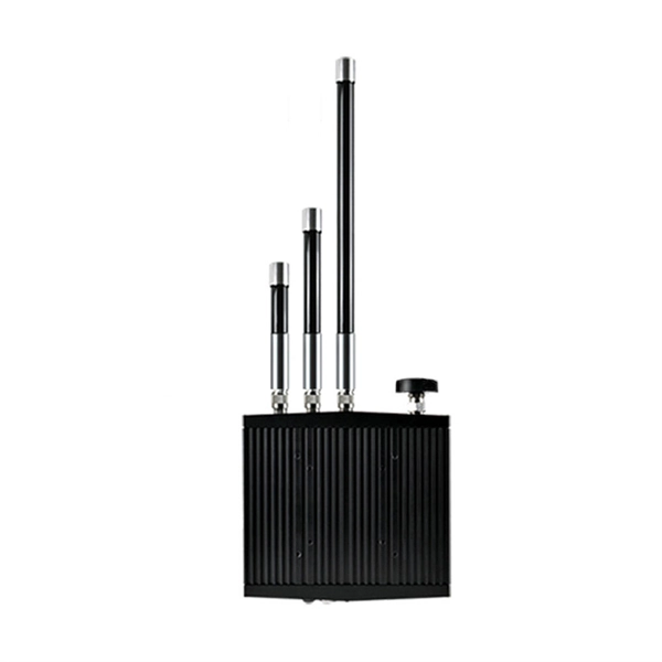
An AMR unit can be retrofitted onto an existing meter to automatically ping the meter and get a current reading. The meter data is transferred to a database where it can be monitored, analysed and used to bill customers based on actual consumption. An AMR (Automated Meter Reading) meter collects data from your gas, electricity, or water meter and transmits it to a central platform in real time. It eliminates manual readings and gives you instant access to consumption data. We offer industry-leading SmartPoint ® modules that read and store. With our Automated Meter Reading (AMR) systems, you can automatically capture water consumption and status data from water meters just by walking or driving by with mobile reading software that collects data and synchronizes with BEACON ® SaaS hosted software. One Comprehensive. The meter communicates to its collection point using 900 MHz mesh network topology. Automatic Meter Reading (AMR) Systems are technological solutions that enable the remote and automated reading of meter data for energy sources such as electricity. We support you with a powerful, modular radio technology that delivers high-frequency energy data - with stable transmission, long range and low maintenance. As a water and energy provider you need a flexible solution for remotely reading consumption meters that is tailored to your precise needs.
[PDF]
Absolute optical power calibration of optical power meters, radiometers and photodiodes: From 350 to 1650 nm in 5 nm steps, power range +10 to -60 dBm / 10 mW to 1 nW, with least uncertainty of 0.06 dB.
[PDF]
An optical power meter (OPM) works by converting light energy into electrical energy using a photodiode sensor. When light from a fiber optic cable hits the sensor, it generates a small electrical current related to the light's strength. Optical power meters are a key element in the optimization and maintenance of such optical networks and of their components. In this article, learn: What is an optical power meter? An optical power meter (OPM) measures the power levels of light signals in devices that transmit data or power using. An optical power meter (OPM) is a device used to measure the power in an optical signal. The term usually refers to a device for testing average power in fiber optic systems. It measures the optical power transmitted through a fiber, helping to verify if the light signal is strong enough for communication. Beginners may find it complex, but understanding its function makes it. This article provides a comprehensive overview of optical power meters, instruments used to measure the power of light beams. It details the main components, including sensor heads and display units, and explains the two primary sensor technologies: robust thermal sensors for high powers and. A fiber-optic power meter is a quantitative measurement instrument, not a diagnostic tool by itself.
[PDF]
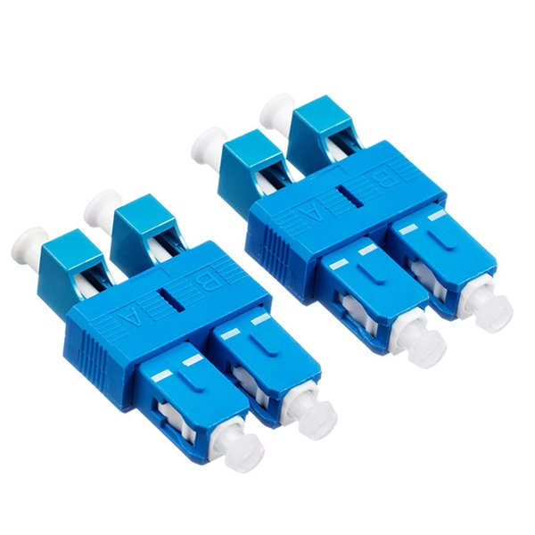
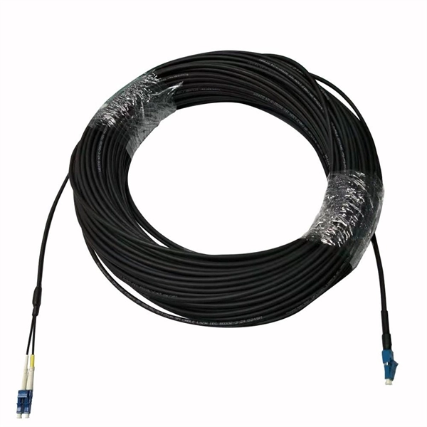
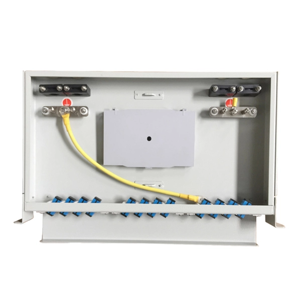
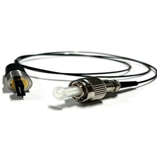
Typical rates range from $0. 00 per ft depending on terrain, access, and required precision for termination. Basic — 1,000 ft single-mode run indoors with minimal termination: Cable $0. 00/ft, Permits $150, Accessories $100. Total ≈ $2,650–$3,100. 🔥Buy Fiber Cables products online from DanounTech the best tech store📱 in Lebanon🇱🇧 | find low prices everyday, and enjoy fast delivery🚚. DanounTech | LEBANON. Fiber optic solutions (drawers, panels, connectors. ) | Fibre optic cables | !. 50-meter, 2-core single-mode fiber optic cable with APC (Angled Physical Contact) connectors, providing low-loss, low-reflection performance for high-speed data transmission. Ideal for FTTH, telecom, and network infrastructure requiring reliable duplex connectivity. Each cable features advanced fiber optic technology to deliver superior performance, low latency, and high bandwidth. Anixter is your source for Indoor/Outdoor Fiber Optic Cable products. olx Lebanon offers online local classified ads for Fiber Optic. Post your classified ad in various categories like mobiles, tablets, cars, bikes, laptops, electronics, birds, houses, furniture, clothes, dresses for sale in Lebanon.
[PDF]
It performs error detection and alarm monitoring, serving as an essential tool for bit error testing in R&D and production of optical modules/ devices. Bit Error Ratio Tester is an instrument used to test and analyze bit error ratio in digital transmission systems, fiber optic communication systems, and digital microwave communication systems. Dimension Technology's BERT800 bit error tester series offers a comprehensive solution for testing and verifying high-speed optical transceiver modules. OPTELLENT is a provider of broadband test and measurement solutions for communications. The Company's test & measurement solutions are used in product development, manufacturing. As transmission rates continue to accelerate, accurately measuring bit error rates in optical modules is crucial to ensure reliable performance. There are three interchangeable slot boards which include QSFP, SFP+ and SFP ports separately. QSFP, SFP+ and SFP ports follow QSFP MSA, SFP+ MSA and SFP MSA. The user interface allows you to individually monitor bit error rate, error count and timer by connecting to PC via USB cable. In high-speed digital communication systems, even the smallest bit-level error can compromise performance, reduce efficiency, or lead to costly rework.
[PDF]
In this video, we'll show you how to connect an energy meter to a distribution board (DB) safely and efficiently. energy meter connection with distribution box How to Connect an Energy Meter to Your Distribution Box Easily Steps to Properly Connect Your Energy Meter to a Distribution Box. Site/existing equip info - SFH (1 story, no basement, just crawlspace) w/ attached garage. 200A main service (Leviton panel). Covers wiring, placement, standards, and expert tips for a compliant setup. A distribution box is the heart of any electrical system. It takes the incoming power and safely distributes it to different circuits throughout your building. I am going to start digging a trench to run underground cable from a service pole breaker box to a well house; the distance is 60 feet. The breaker is a 240 V 2-pole 20-20 which will run to the well house water pump pressure switch. The present UF 2-10 AVG with ground cable runs two inches under. An electric meter box wiring diagram is a visual representation of the electrical connections and circuits involved in connecting an electric meter to the rest of the electrical system in a building. The diagram provides a clear and concise overview of how the meter is connected to the electrical. Limited the meter location from pad mount transformer for PSO. APCo and TX do not allow unistrut for installations. 7/2020 Revised Figure 15. Added wording for consistency with Section 8 of document.
[PDF]