Check the diagnostic information, which shows that the received optical power is low, with a threshold of -3 to -23. 01, currently at -22. Once it exceeds the threshold, an alarm will be triggered. Troubleshoot the link, and if the link is normal, replace the optical. Run the display interface transceiver verbose command in the user view to check whether the transmit optical power (Tx Power) of the interface is within the allowed range. If yes, collect alarm, log, and configuration information, and contact technical support personnel. If the optical module is. An optical module was faulty. Cause 2: Output Optical Power Too High. Services on the optical module may be affected, which may cause bit errors, error packets, or even service interruption. During use, reading optical module information helps understand its real-time operating status, enabling faster troubleshooting of link abnormalities. The following uses the. The International Photonics & Electronics Committee (IPEC) is an international standards organization that is committed to developing open optoelectronic standards and delivering strategic roadmap reports. IPEC focuses on standardizing solutions in optical chips, optical/electrical components, and. The optical module on the port generates an alarm. Often referred as I²C, I2C, IIC (Inter-Integrated Circuit), MDIO (Management Data Input/Output) or CMIS (Common Management Interface Specification), these serial bus.
[PDF]
NADDOD Cisco compatible OSFP-800G-2xFR4 Optical Transceiver Module is a high-speed, low-latency solution designed for 800GBASE-2xFR4 Ethernet with link lengths up to 2km over single-mode fiber (SMF) using dual duplex LC connectors. This transceiver is compliant with IEEE 802. 3cu, OSFP MSA standards. Class1/1M Standard Product, Compliant with RoHS Environmental Protection Standards (Lead-Free). DDM (Digital Diagnostic Monitoring) Supported. 30-Day Free Return, 1-Year Free Replacement, 3-Year Warranty, Lifetime After-sales Technical. The QSFPTEK QT-OSFP-400GSi-DR4 is a transceiver module designed for 500m optical communication applications, and it is compliant with OSFP MSA and IEEE 802. The silicon photonics transceiver is based on a new state-of-the-art silicon photonics (SiPh) platform. It uses SiPh chips that. Core Competence: Strong design capabilities: 1. The R&D team has more than ten years of development experience, optical design simulation, high-speed circuit design, radio frequency simulation, structural design and thermal simulation, large-scale multi-series optic transceiversautomated test system. 2x 400G FR4 OSFP 800G transceiver module supports a max data rate of 850Gbps. The 800 Gigabit Ethernet signal is carried over 4 wavelengths at 1271nm, 1291nm, 1311nm, and 1331nm. QSFPTEK manufactured 2x. 800GBASE-2FR4 OSFP PAM4 1310nm 2km DO.
[PDF]
HUAWEI WDM replacing the optical module video shows you how to replace an optical module. HUAWEI WDM Documentation:. Never look directly into an optical module or the ends of optical fibers. Optical modules and connected fibers emit laser radiation that will cause eye damage. A switch must use optical or copper modules that have been certified for use on Huawei S switches. HUAWEI WDM. Maintenance quick reference section, in which some common maintenance commands, precautions and related reference materials are given. It mainly includes the following contents: 2. Network management part: In this part, some common operations and common problem solving of NES, RMS and T2000. This article summarizes several solutions for using optical modules with switches and common problems encountered during usage, along with specific solutions. Huawei S5720-32P-EI-AC Switch II. How to Configure Optical Ports on Huawei S5720-32P-EI-AC Switch? Problem: All optical ports cannot be. Do not look into bores of optical modules or connectors of optical fibers without eye protection. The device must use optical or copper modules recommended on the configurator because non-Huawei-certified optical. Optical Module quality control-Test Procedure In order to ensure that the optical module we deliver do not have compatibility problems. More Optical Module quality control-Test.
[PDF]
The optical budget refers to the maximum allowable signal loss between the transmitter and receiver in a fiber-optic link. It ensures that the received signal is strong enough for the equipment to process data without errors. Calculated in decibels (dB), it is the difference between the. After measuring the loss of a fiber link, you now have to determine if that fiber link loss is acceptable or not. You can either compare this loss value to the application requirement or calculate the expected loss based on how many connectors and splices are in the link along with the length of. Optical module channel loss resistance refers to the maximum optical path attenuation that an optical transceiver module can tolerate while still maintaining compliant signal integrity, error performance, and link stability. There are many reasons for optical fiber loss, such as optical fiber material's absorption/scattering of light energy, bending.
[PDF]
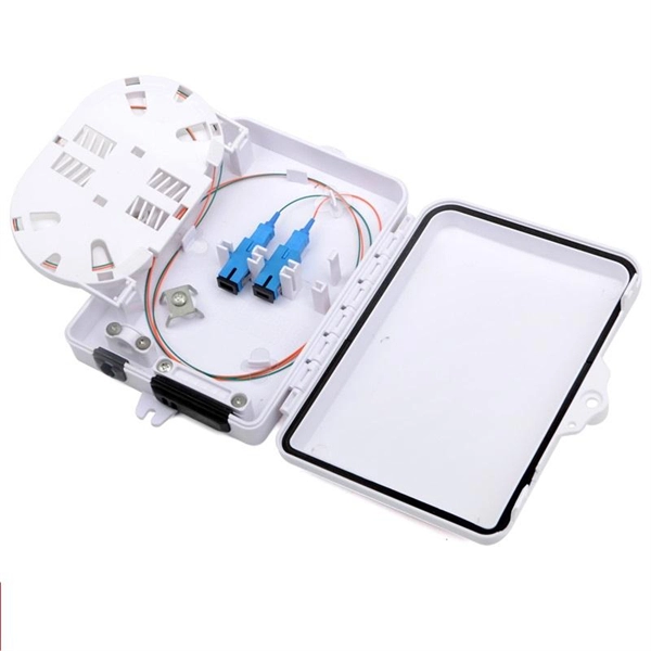
These modules typically consist of a laser or LED transmitter, a photodiode receiver, and supporting electronics. Optical modules are compact devices that convert electrical signals into optical signals and vice versa. They are used in fiber optic communication systems to transmit data over long distances with minimal loss and interference. The Cisco NCS 2000 Series encompasses platforms from Cisco NCS 2002 onwards. In intelligent computing centers built around large-scale GPU clusters, network bandwidth, latency, and reliability directly determine the efficiency of AI training, big data processing, and other tasks. As a core component connecting servers, switches, and storage systems, optical modules play a. What is an SFP? SFP (Small Form-factor Pluggable) is a compact, hot-pluggable network interface module used to connect network devices (switches, routers, firewalls) to fiber optic or copper cables. The OLT is installed at the headend and each OLT port connected into the fiber to the designated service area and the splitters installed to serve the intended users. Operating at the physical layer of the OSI model, optical modules are core devices in optical.
[PDF]
A multimode APC (Angled Physical Contact) connector is a fiber optic connector designed for high-performance optical signal transmission. Its key feature is the 8° angled polish on the connector's end face. SN®-MT They support both single-mode (SM) and multimode (MM) fibers and are widely used in space-constrained environments requiring high. The QSFP-100G modules are our latest generation of 100G transceiver modules solution based on a QSFP form factor. (See Figure 1) Figure 1. ● Hot-swappable input/output device that plugs into a 100G Gigabit Ethernet Cisco QSFP port. Similar to standard APC connectors, this design effectively reduces back reflection by. Corning manufactures a full line of high-performance APC (angle polish connector) fiber connectors and adapters. Corning 8-degree APC connectors are fully intermateable with standard NTT APC products and deliver long-term stability under a range of applications and conditions. Each type varies by shape, polish (APC, PC, or UPC), and return loss performance, which affect PC, UPC, and APC Polish Styles: What's the.
[PDF]

To connect an optical cable to an SFP module, use the appropriate patch cord (e., LC-LC, SC-LC, etc. The patch cord must match the fibre type – single-mode or multi-mode. Once connected, verify that the port activity indicator is on and run diagnostic commands to check the. Small Form-factor Pluggable modules (SFP module) are the workhorses of modern network connectivity, enabling flexible fiber optic or copper links between switches, routers, firewalls, and servers. Whether you're upgrading bandwidth, replacing a faulty unit, or reconfiguring your topology, knowing. Connecting your fiber optic cable to an SFP (Small Form-factor Pluggable) module can seem daunting if you're unfamiliar with networking hardware. However, with a bit of guidance, the process is straightforward. Remove the dust caps from the SFP module and the fiber optic cable. Today, we will discuss the best methods to connect SFP to fiber optic patch cables. To connect a fiber optic cable to SFP optical module, first ensure the SFP is fully inserted into the network port until it "clicks", then remove the dust caps from both the SFP and the LC fiber optic connector. Laser Compliance The fiber-optic SFP+ / SFP28 modules contain a laser that is classified as a “Class 1 Laser Product” in accordance with US FDA regulations and the IEC 60825-1. The product does not emit hazardous laser radiation. The module is fully seated when you hear a click. (SFP+ and SFP28.
[PDF]
This optical module speed guide helps data center and campus engineers map 1G, 10G, 25G, 40G, 100G, 200G, and 400G optics to real hardware constraints: form factor, wavelength, reach, transceiver signaling, and DOM behavior. Use it to standardize procurement and reduce trial-and-error across. Strategic conclusion: Italy's 400G optical module market is positioned for rapid expansion driven by digital transformation, 5G deployment, and regional infrastructure investments. Success hinges on localized supply chain development, technological differentiation, and strategic partnerships. Current products support 100Gbps to 1200Gbps, including pluggable 400ZR/ZR+. All of Acacia's revenue is designated as Telecom and designated as "Other". Accelink builds optical modules across the transmission, datacom, access, and mobile broadband markets. Accelink's datacom revenue is included in. By 2025, operators moved past 400G, with 800G becoming the mainstream, and early pilots pushing into 1. 6T 224 Gb/s PAM4 links. Yet supply has lagged demand. In early 2024, primary North American markets showed only 2. Switch ASICs now integrate HBM and extend fabrics up to 60 miles to. Upgrade to 100G or 400G optics and save. Cisco Transceiver Modules - Learn product details such as features and benefits, as well as hardware and software specifications. The options may be chosen on the product page Select options This product has multiple variants.
[PDF]
Our in-depth market data report on Optical Module Industry. Explore verified statistics and the latest research., May 04, 2026 (GLOBE NEWSWIRE) -- GlobalFoundries (Nasdaq: GFS) (GF) today announced the introduction of its SCALE™ optical module solution for co-packaged optics (CPO). GF's SCALE solution, or Silicon photonics Co-packaged Advanced Light Engine solution, is the industry's first Optical. Major optical modules manufacturers and suppliers: Innolight, Eoptolink, Huagong Tech, Linktel, Accelink, CIG ShangHai CO. Upstream optical devices manufacturers and suppliers: TFC, T&S Communications, Advanced Fiber Resources, Borui Technology, Optowide Technologies. With support for both coarse and dense wavelength-division multiplexing (CWDM. The figure below illustrates the changes in the TOP10 list of optical transceiver suppliers over the last 15 years. A majority of the Japanese and US-based suppliers exited this market by 2020, while Chinese vendors improved their rankings. Innolight and Eoptolink focused their business on service. Optical module demand is being pulled in two directions at once, faster bandwidth for dense networks and tighter constraints on power, security, and lead times. With global R&D projected to exceed $2. 1 billion by 2025 and 35 percent of manufacturers reporting lead times beyond 12 weeks, the. MALTA, N.
[PDF]
In this guide, we will walk you through the step-by-step process of installing and removing SFP transceiver modules correctly and safely. Small Form-factor Pluggable modules (SFP module) are the workhorses of modern network connectivity, enabling flexible fiber optic or copper links between switches, routers, firewalls, and servers. SFP Transceiver Module – Choose the appropriate module based on your network requirements (e. SFP transceivers allow for the transmission and reception of optical signals in networking devices such as switches, routers, and media converters. In. SFP module installation and removal are straightforward processes. However, you might need to refer to the datasheet or user manual of any new transceivers to familiarize yourself with their properties and the latching mechanism. What Should You Know Before Installing and Removing Modules? Avoid. Whether you're connecting switches in a data center or linking a server to your network, SFP (Small Form-factor Pluggable) modules are the unsung heroes that make it all possible. These compact, hot-swappable transceivers allow you to customize your network connections for copper or fiber optic. Before installing an SFP or SFP+ module, we need to know some caution tips first. ● Avoid allowing dust and other contaminants to enter the optical bores of the SFP or SFP+ module because the optics do not function properly when blocked by dust. After removing the optical cables, protect them by.
[PDF]
BiDi SFPs connect to a fiber cable using only one simplex port, whereas standard transceivers have duplex fiber ports. BiDi transceivers. BiDi optical modules can do this by utilizing full-duplex communication over a single fiber strand via two wavelengths. By reading this blog, you will understand how SFP BiDi technology allows you to save fiber, reduce costs, and simplify installation while enabling your network to increase. BiDi transceiver, a compact optical transceiver with WDM (wavelength division multiplexing) technology and SFP multi-source protocol (MSA) compliance, allows fast data transmission using a single fiber optic for both sending and receiving signals, saving resources and cutting infrastructure costs. This approach effectively doubles the capacity of existing fiber installations while. A Bidirectional (BIDI) optical module is a compact, high-performance transceiver used in fiber optic communication systems. Unlike traditional optical modules that require two fibers (one for transmitting and one for receiving), a BIDI module uses only a single fiber strand for bidirectional data. A BiDi (Bidirectional) optical module adopts WDM (Wavelength Division Multiplexing) bidirectional transmission technology, enabling simultaneous bidirectional transmission within an optical channel over a single optical fiber. Unlike conventional optical modules (which have two fiber jacks, as.
[PDF]
A PON module, or Passive Optical Network module, serves as a pivotal device in telecommunications networks, facilitating the transmission of data, voice, and video signals over fiber optic cables. What is a PON Module? A PON module is an optical transceiver specifically designed for Passive Optical Network applications. Unlike active optical components requiring power, PON leverages passive splitters, making the modules in the Optical Line Terminal (OLT) at the provider's end and the Optical. Passive optical networking (PON), like active optical networking, uses fiber-optic cabling to provide Ethernet connectivity from a main data source to endpoints. While there are many subtle differences, a clear distinction between active optical networking and PON topology is PON's use of a. A passive optical network (PON) is a fiber‑based access network that uses unpowered optical components to deliver high‑speed connectivity from a service provider to many end users. In practice, PONs are typically used for the last mile between Internet service providers (ISP) and their customers. Read on to learn everything you need to know about passive optical networks and why they might just be the solution to.
[PDF]
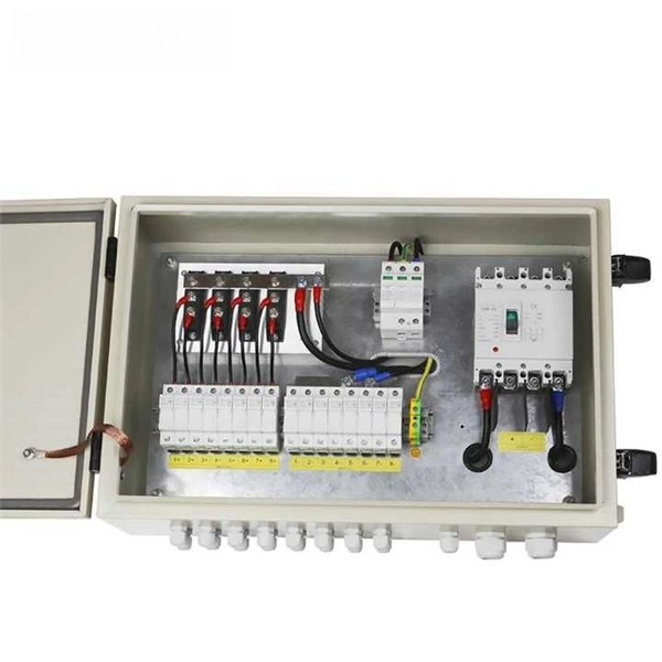
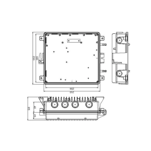
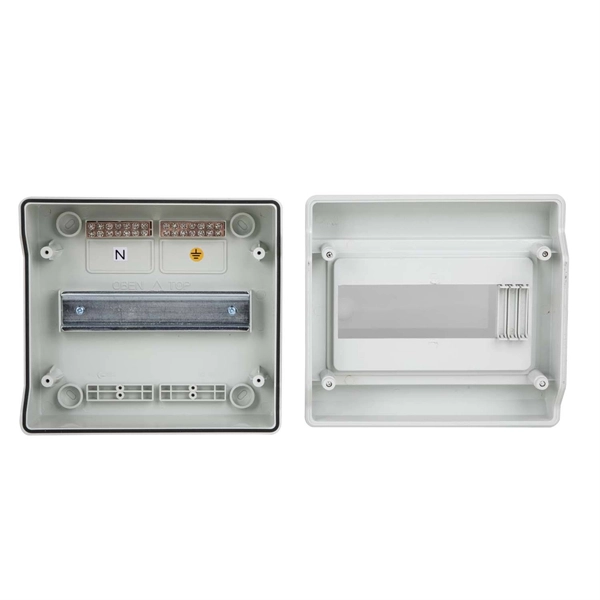
A Distribution Box, commonly known as a DB Box, serves as the central point for safely distributing electrical power from a main supply to multiple downstream circuits. It houses protective devices such as circuit breakers or fuses, ensuring both equipment protection and user. This ultimate guide explains what a distribution box does, its internal components, common types, real-world applications, and how to select the right DB Box for your project. We also highlight how reliable manufacturers like NUOMAK support stable, compliant, and cost-effective power distribution. At the heart of this network lies a power distribution box, the component responsible for dividing and controlling electricity as it moves from the main source to multiple end-use circuits. Within larger systems, the box often works in tandem with a distribution board, ensuring each circuit branch. A power distribution box is a key part of any electrical system. It takes electricity from the main source and safely sends it to different circuits in a home, office, or industrial setup. Without it, managing power would be messy, unsafe, and inefficient. But what exactly is a power distribution box, and why is it so essential in our daily lives? The DB panel board controls the flow of electricity. In the safe and effective supervision of electrical systems, distribution boxes may be the last quite unnoticed yet they are extremely fundamental part.
[PDF]
Grounding of the units: Attach a ground wire from one of the threaded studs (A) at the bottom of the housing, to the mounting plate (B). The ground resistance between. This section applies to grounding of transmission and distribution lines and equipment for the purpose of protecting employees. Note to paragraph (a): This section covers. Learn what OSHA requires for electrical grounding in general industry and construction, and what violations can cost you. OSHA's grounding requirements are spelled out primarily in two sets of regulations: 29 CFR 1910 Subpart S for general industry workplaces, and 29 CFR 1926 Subpart K for. Power from factory ground must be installed by a qualified electrician. Each DISTRIBUTION BOX and controller must be grounded. On the US market, a 5. 26 mm 2 (10 AWG) ground wire must be used, and in all other markets a 6 mm 2 must be used. The lockout/tagout procedure must consider several factors, one of which is grounding. Sometimes, installing temporary protective grounding is necessary. Whether you're a seasoned pro or just starting out, this comprehensive guide will give you practical.
[PDF]

One-line diagrams and detailed network data (lines, transformers, buses). Short-circuit models, including fault current calculations under various system configurations. Protective relay settings and coordination curves. Historical. presentation of protection and control relaying. The report will identify methodology behind these practices, present issues raised by the integration of microprocessor relays and the internal logic and external communication configurations, ying. Schematic diagrams of protection relays are essential tools for power engineers in the power generation, transmission, and distribution industry. This includes AC schematics and DC schematics and diagrams that prominently feature relaying. There are other equally important types of drawings that are not the subject. Power System Protective Relays: Principles & Practices Presenter: Rasheek Rifaat, P. Eng, IEEE Life Fellow IEEE/IAS/I&CPSD Protection & Coordination WG Chair Jacobs Canada, Calgary, AB rasheek. com IEEE Southern Alberta Section PES/IAS Joint Chapter Technical Seminar - November 2016. Recognized under 2(f) and 12 (B) of UGC ACT 1956 (Affiliated to JNTUH, Hyderabad, Approved by AICTE - Accredited by NBA & NAAC – 'A' Grade - ISO 9001:2015 Certified) Maisammaguda, Dhulapally (Post Via. Kompally), Secunderabad – 500100, Telangana State, India To introduce all kinds of circuit.
[PDF]