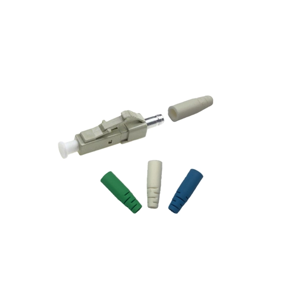
The short answer is no - RJ45 connectors are designed for electrical Ethernet signals, while fiber optics transmit light pulses through glass or plastic. However, modern networks often combine both technologies. A combo port, also known as an optoelectronic multiplexing interface, is a photoelectric composite port with two kinds of Ethernet interfaces (RJ45 port and SFP port) on an Ethernet switch. In other words, it is a compound port that can support two different physical layers and share the same. Optical ports on switches typically require the insertion of optical modules for data transmission over fiber optics. However, these two different physical ports can not be used at the same time. If you wake up the RJ45 port, the corresponding SFP port will. Ensuring seamless interoperability and compatibility between optical transceiver modules and network devices is crucial for maximizing network performance, reducing downtime, and controlling operational costs. This guide dives deep into the core aspects of optical transceiver compatibility, common. SFP (Small Form-factor Pluggable) is a compact, hot-pluggable network interface module used to connect network devices (switches, routers, firewalls) to fiber optic or copper cables. Think of it as the “translator” for your network equipment, converting electrical signals into optical signals.
[PDF]
Positive busbars, which collect all positive connections. Key Steps: When wiring a pair of 12V busbars, connect the positive terminal of each load to a stud on the positive busbar and their negative terminal to a stud on the negative busbar. 5' above batteries on inside of cockpit combing below decks. Install one new positive bus bar beside the negative one separated by about two inches 3. Positive and negative busbars are physically identical apart from the red/black colours used by some manufacturers to visually differentiate between. A Complete Guide to Battery Terminal Connector Types The store will not work correctly in the case when cookies are disabled. JavaScript seems to be disabled in your browser. For the best experience on our site, be sure to turn on Javascript in your browser. Skip to Content Blog Sign In Create an. This image illustrates a standard car battery with top post terminals and labeled connectors for the positive (+) and negative (–) ends, emphasizing safe and correct installation. A battery terminal connector is a fitting or clamp that attaches to a battery's terminal to connect a cable. In other. Both positive and negative terminals are the soul of the electrical system of the car, allowing the engine to start while keeping other components running. The catch? Mix-up or loose connection can cause electrical failure, drained batteries, and damage to wiring. This blog guides you how the two.
[PDF]
National Electrical Code (NEC) allows up to three grounding conductors to terminate under one lug on a grounding bus, provided it is listed for such use. This is covered under section 110. Correct grounding of services depends upon understanding the definition and role of the grounded conductor. The neutral conductor is typically the grounded conductor connected to the system's neutral point, carrying current under normal operation. Grounding electrode conductors must be connected at. Sometimes if I have a 3 or 4-gang plastic nail-on switch box that has a bunch of NM cables, when I'm making up the box rather than using a big blue wire-nut for my grounds I'll separate the grounds into 2 groups and use red/tan wirenuts instead, especially if there's 2 circuits in the box. This configuration may not comply with current electrical. Learn how to connect equipment grounding conductors to receptacles and keep their continuity in boxes. The basic rule achieves this through an equipment grounding jumper; four exceptions. A grounding terminal or grounding-type device on a receptacle, cord connector, or attachment plug may not be used for purposes other than grounding. (b) Branch circuits — (1) Identification of multiwire branch circuits. When conductors are spliced inside a box or terminated to.
[PDF]
Different solar panels will have information on the sticker on the back showing how to test. (1) Using a voltage meter, locate the open-circuit voltage (Voc) on the specifications label on the back of your solar panel. Write it down for late. Different solar panels will have information on the sticker on the back showing how to test. (1) Using a voltage meter, locate the open-circuit voltage (Voc) on the specifications label on the back of your solar panel. Write it down for later use. To measure the voltage of a DC circuit, you should prepare your multimeter by plugging the black probe. The short circuit current (Isc) on a circuit panel is located on the specifications label on the back of the panel. Record this number for later use. To prepare your multimeter to measure amps, move the red probe to the amperage terminal and set your multimeter to the amp setting (A). If your multimeter is not automatic-ranging, be sure to choose t. You can also measure the voltage of a photovoltaic panel (PV Current) by connecting it to a charge controller. It's possible to use a multimeter to determine how much current your solar panel is outputting, but you'll need an extra piece of equipment first. 1. Solar charge controller 2. Battery Plug the solar charge controller into the battery. Con.
[PDF]
Use the command display transceiver to view the optical module information of all optical ports, and use the command display transceiver interface interface-type interface-number to view the optical module information of a specific optical port. Related Information Video Identify a Huawei-Certified Optical Module Run the display transceiver [ interface interface-type interface-number | slot slot-id ] [ verbose ]. Here is an example on how to query or display optical power of an interface in a Huawei Router. This is tested using NetEngine40E Universal Service Router or NE40E running version 8. The specific viewing information is as follows:. Optical modules are widely used in switches, network interface cards (NICs), routers, and other communication devices. During use, reading optical module information helps understand its real-time operating status, enabling faster troubleshooting of link abnormalities. Transceiver Type : 1000 _BASE_SX_SFP Connector Type :LC Wavelength(nm) : 850 Transfer Distance(m) : 300 (50 um), 150. We want to troubleshoot transceiver on Huawei router, Huawei switch, Huawei systems. 1 Show details, warning etc. from transceivers Check “Alarm information” section for warnings, LOS Alarm means no inbound signal, execute display this to check shutdown mode, execute undo shutdown if necessary.
[PDF]