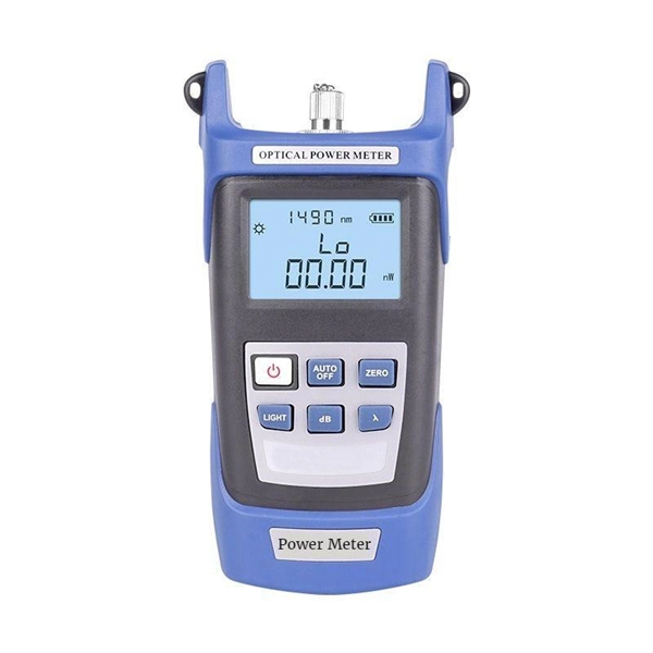
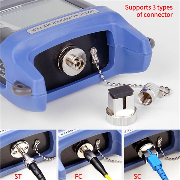
An optical power meter is an electronic device that measures the power of an optical signal. It helps engineers verify the performance of optical fiber systems, ensuring that the signal strength meets requirements, and is an essential tool for communication network maintenance and. An optical power meter (OPM) is a device used to measure the power in an optical signal. Other general purpose light power measuring devices are usually called radiometers, photometers, laser power meters (can be. An optical power meter (OPM) measures the power levels of light signals in devices that transmit data or power using light. The term "optical power meter" may sound generic, but in popular usage, it specifically implies a fiber optic power meter. For light power measurements outside the field of. Optical Power Meters (OPMs) are crucial instruments in the field of optical sensors and fiber optic communications. It provides an expert-curated supplier directory, buyer-focused technical background information, and structured selection criteria to support professional procurement decisions. It measures optical power directly, and it is also used in loss testing when paired with a stable light source.
[PDF]
An optical power meter (OPM) works by converting light energy into electrical energy using a photodiode sensor. When light from a fiber optic cable hits the sensor, it generates a small electrical current related to the light's strength. Optical power meters are a key element in the optimization and maintenance of such optical networks and of their components. In this article, learn: What is an optical power meter? An optical power meter (OPM) measures the power levels of light signals in devices that transmit data or power using. An optical power meter (OPM) is a device used to measure the power in an optical signal. The term usually refers to a device for testing average power in fiber optic systems. It measures the optical power transmitted through a fiber, helping to verify if the light signal is strong enough for communication. Beginners may find it complex, but understanding its function makes it. This article provides a comprehensive overview of optical power meters, instruments used to measure the power of light beams. It details the main components, including sensor heads and display units, and explains the two primary sensor technologies: robust thermal sensors for high powers and. A fiber-optic power meter is a quantitative measurement instrument, not a diagnostic tool by itself.
[PDF]
To meet the needs of multi-way power distribution applied to high-power solid-state sources, a multi-way power distribution device based on coaxial waveguide is designed and studied. In this work, two dynamically tunable power dividers using waveguide ENZ media are proposed by precisely modulating the internal magnetic field and the widths of the output waveguides. The first approach features a mechanically reconfigurable ring-shaped ENZ waveguide. By analyzing the transmission characteristics of coaxial waveguides and by applying the theory of impedance. In this paper, an E -plane stepped-impedance transformer and Y-junction bifurcation are used to form a waveguide power divider with ceramic substrate loaded with thin film resistors. This structure is realized high isolation in V-band by inserting a ceramic substrate at the H -plane center of the. A numerical model of an equal power divider based on the 4-branch single-mode waveguide is proposed. This proposed design does not require extra fabrication process and supplementary structure modification compared to other typical multibranch waveguides. The condition of uniform output power.
[PDF]
Your AC unit won't turn on after a breaker trips, so check your fuse box and reset the breaker to repair an AC unit. Costs range from $130 to $3,000 to repair an AC unit, with average costs around $350 based on the repair. Use the information below to estimate how much electricity an appliance is using and how much the electricity costs so you can decide whether to invest in a more energy-efficient appliance. Simply connect any appliance to the Kill A Watt EZ, it will then assess how efficient each appliance really is. They were not intended to be prescriptive in terms of what people should build, but they do stipulate important dos and don'ts – many of which. Atomic Energy Act of 1954, secs. 11, 53, 63, 65, 81, 103, 104, 161, 170H, 182, 186, 223, 234, 274, 1701 (42 U. 2014, 2073, 2093, 2095, 2111, 2133, 2134, 2201, 2210h, 2232, 2236, 2273, 2282, 2021, 2297f); Energy Reorganization Act of 1974, secs. 5841, 5842); Low-Level. EPA and the Centers for Disease Control and Prevention (CDC) agree that there is no known safe level of lead in a child's blood. Taking action to reduce these exposures can improve outcomes. Lead is harmful to health, especially for children. On this page: General Information about Lead in Drinking.
[PDF]
In this video, we'll show you how to connect an energy meter to a distribution board (DB) safely and efficiently. energy meter connection with distribution box How to Connect an Energy Meter to Your Distribution Box Easily Steps to Properly Connect Your Energy Meter to a Distribution Box. Site/existing equip info - SFH (1 story, no basement, just crawlspace) w/ attached garage. 200A main service (Leviton panel). Covers wiring, placement, standards, and expert tips for a compliant setup. A distribution box is the heart of any electrical system. It takes the incoming power and safely distributes it to different circuits throughout your building. I am going to start digging a trench to run underground cable from a service pole breaker box to a well house; the distance is 60 feet. The breaker is a 240 V 2-pole 20-20 which will run to the well house water pump pressure switch. The present UF 2-10 AVG with ground cable runs two inches under. An electric meter box wiring diagram is a visual representation of the electrical connections and circuits involved in connecting an electric meter to the rest of the electrical system in a building. The diagram provides a clear and concise overview of how the meter is connected to the electrical. Limited the meter location from pad mount transformer for PSO. APCo and TX do not allow unistrut for installations. 7/2020 Revised Figure 15. Added wording for consistency with Section 8 of document.
[PDF]
Calibration & Repair services in Ireland. 5 day turn around with competitive pricing! View full electrical test and measurement equipment list here. is an independent calibration laboratory focused on meeting the total quality requirements of industry. Proper calibration of today's sophisticated test and measurement equipment is essential for preserving measurement accuracy, complying with international standards. Parameters covered include; Temperature, Humidity, Dewpoint, Various Gases, Pressure, Electrical, Weights & Scales, Analytical and some Specialist calibrations. Calibration is performed using the very latest Calibration Equipment/Standards & Calibration/Asset Management Software. Fast Efficient. PTM Calibration offers a wide range of services that complement our core business. We aim to be your one stop shop for all your calibration, test & measurement needs. From major blue chip companies & medium enterprises to small companies and sole traders. Including: aerospace, pharmaceuticals. OptiCal Sciences are an authorised service centre with service, repair and calibration experience and procedures for an extensive variety of models from a wide range of manufacturers.
[PDF]
A PON module, or Passive Optical Network module, serves as a pivotal device in telecommunications networks, facilitating the transmission of data, voice, and video signals over fiber optic cables. What is a PON Module? A PON module is an optical transceiver specifically designed for Passive Optical Network applications. Unlike active optical components requiring power, PON leverages passive splitters, making the modules in the Optical Line Terminal (OLT) at the provider's end and the Optical. Passive optical networking (PON), like active optical networking, uses fiber-optic cabling to provide Ethernet connectivity from a main data source to endpoints. While there are many subtle differences, a clear distinction between active optical networking and PON topology is PON's use of a. A passive optical network (PON) is a fiber‑based access network that uses unpowered optical components to deliver high‑speed connectivity from a service provider to many end users. In practice, PONs are typically used for the last mile between Internet service providers (ISP) and their customers. Read on to learn everything you need to know about passive optical networks and why they might just be the solution to.
[PDF]
Full Technical Specifications: Explore our complete range of directional and dual directional couplers, featuring ultra-wideband operation from 0. This catalog details models with coupling values from 5 dB to 50 dB and power ratings up to 500 Watts. How does 6W market outlook report help businesses in making decisions? 6W monitors the market across 60+ countries Globally, publishing an annual market outlook report that analyses trends, key drivers, Size, Volume, Revenue, opportunities, and market segments. This report offers comprehensive. IPP's directional couplers offer some of the widest bandwidths at the highest power levels in the industry. These directional couplers are available in frequencies from 1 MHz., in power. Directional couplers are critical components in radio frequency (RF) and microwave systems, used to split or combine signals while maintaining signal integrity. These passive devices allow a signal to be directed from one port to another, with a portion of the signal being coupled to an auxiliary. We are an RF / Microwave / Wireless Telecom Manufacturer for component, modules and systems. We offer the widest range and best performance RF Directional Couplers and Quadrature Hybrids in the world, extremely aggressive pricing structure. RF directional couplers often. CorechTEK's Directional Couplers are engineered for precise RF and Microwave signal monitoring and power sampling. CorechTEK Couplers.
[PDF]

The actual number of optical modules used primarily depends on the following factors. Discrepancies in Calculating the Ratio of Optical Modules to GPU-The Varying Usage Quantity Due to Different Networking Architectures. Network Card Model. GPUs such as the A100, H100, and upcoming GH100 require high-speed optical interconnects to link thousands of GPU nodes, enabling large-scale AI model training and inference. Network Card Model It mainly includes two network cards, ConnectX-6. Traditional optical transceivers, especially in 400G and 800G deployments, generate significant heat and demand substantial power just to keep the lights blinking. 1) NIC Models Mainly includes two types of network cards, ConnectX-6 (200Gb / s, mainly used with the A100) mainly used optical modules are MMA1T00-HS (200G Infiniband HDR QSFP56 SR4 PAM4 850nm 100m) and ConnectX-7. Two complementary approaches are used to grow these systems: scale-up (tightly coupling many accelerators as one unit) and scale-out (networking multiple units across racks or clusters). In both cases, optical connectivity is playing an increasingly vital role. Below, we explain the trends in. While the industry-standard OSFP (Octal Small Form-Factor Pluggable) module has successfully enabled 400Gbps, 800Gbps, and 1. 6Tbps optical pluggable modules , it is limited to 32 modules per Rack Unit (RU), typically requiring 2 RUs to achieve 102. 4Tbps and 4 RUs to reach 204. 8Tbps of switching.
[PDF]
It performs error detection and alarm monitoring, serving as an essential tool for bit error testing in R&D and production of optical modules/ devices. Bit Error Ratio Tester is an instrument used to test and analyze bit error ratio in digital transmission systems, fiber optic communication systems, and digital microwave communication systems. Dimension Technology's BERT800 bit error tester series offers a comprehensive solution for testing and verifying high-speed optical transceiver modules. OPTELLENT is a provider of broadband test and measurement solutions for communications. The Company's test & measurement solutions are used in product development, manufacturing. As transmission rates continue to accelerate, accurately measuring bit error rates in optical modules is crucial to ensure reliable performance. There are three interchangeable slot boards which include QSFP, SFP+ and SFP ports separately. QSFP, SFP+ and SFP ports follow QSFP MSA, SFP+ MSA and SFP MSA. The user interface allows you to individually monitor bit error rate, error count and timer by connecting to PC via USB cable. In high-speed digital communication systems, even the smallest bit-level error can compromise performance, reduce efficiency, or lead to costly rework.
[PDF]
A WDM system uses a multiplexer at the transmitter to join the several signals together and a demultiplexer at the receiver to split them apart. With the right type of fiber, it is possible to have a device that does both simultaneously and can function as an optical add-drop. In fiber-optic communications, wavelength-division multiplexing (WDM) is a technology which multiplexes a number of optical carrier signals onto a single optical fiber by using different wavelengths (i., colors) of laser light. This technique enables bidirectional communications over a. WDM is a fiber optic transmission technique that leverages multiple light wavelengths to transmit data efficiently over a single medium. WDM technology employs different optical wavelengths, or colors, of laser light to multiplex several optical carrier signals onto a solitary optical fiber. Each. There are a lot of people who don't understand the difference between WDM and optical splitter. This allows multiple channels of data to be transmitted simultaneously. WDM technologies allow organizations to place equipment at either end of a fiber pair and combine multiple wavelength channels on a single fiber pair instead of using multiple separate fibers pairs for every separate service. The article explains the fundamental principle and its.
[PDF]
Manufacturer of GIS and GPS/GNSS receivers, theodolites, levels, 3D coordinate measuring and laser systems for measuring distance, position and area. GLM is a certified dealer for optical surveying instruments. Furthermore LM owns a specialized workshop for maintenance of this measurement technology. Our portfolio includes: On the left, all instrument types are listed which are used and offered by GLM in the fields of industrial surveying (3-D. Pursuant to and for the purposes of Articles 7, 13 and 15 of Regulation EU 2016/679 - GDPR, I hereby declare to have read the Privacy statement of Stonex Srl oncerning the processing of my personal data (Purpose A – request of content /information). I express my consent for the processing of my. For many years as an authorized Leica dealer, we offer primarily instruments of this manufacturer. With a LEICA device you buy next to the absolute best quality, a decades-long expertise of one of the world's leading manufacturers of surveying instruments. Upon request we provide liked building. iVISION - Optical measurement products for cable measurement. Profile projector, wire mesh and shadow graph inspection tools. Laser Levels Our speciality is in the Technical sales area and we offer a comprehensive range that now includes Geomax, Leica, Spectra Precision, Laserliner Brand and SECO range. Full Function Smart GNSS receiver equipped with most advanced GNSS board. Our company can recognise the customers.
[PDF]
Locate Fiber Optic Cables suppliers, manufacturers & distributors in Sweden. Interactive map of Sweden provided. Nexans' range of fiber optic cables includes products intended for data and telecommunications as well as industrial applications. Robust cables for national networks, city networks, rural networks and property networks, for installation indoors, outdoors, in ground pipes, in air systems and in. The Swedish Microwave fiber cables are made as ruggedized cables with narrow bend radius and very good performance to fit together with all our RF over Fiber products. They are all single-mode fiber cables and IP 65 classed when mated. Their product range includes robust cables suitable for various environments, ensuring exceptional performance and fire. Eurolan Uni LT fiber cables are used in backbone, distribution networks or in FTTH solutions. Can be laid indoors as it is or outdoors in pipes. 8 mm gel filled loose tube with 2 - 12 fibers; ø 3. Eurolan LT fiber cables are used in backbone. Air Blown Cables are super slim fiber optic cables to be blown into microducts. Ideal for telecommunications, data centres and networking applications, our fibre optic cables are available in single-mode and multimode configurations.
[PDF]
A Thin-Film Filter (TFF) is an optical device that uses multiple layers of dielectric coatings deposited on a substrate to selectively transmit or reflect specific wavelengths of light. It is a fundamental component in modern optical communication systems. The Z-Block is a core optical component used in wavelength division multiplexing/demultiplexing (WDM) systems. Structurally, it is typically composed of several integrated optical elements, including collimating lenses, rhomboid prisms, and specially designed optical mirrors. TFFs are widely used as. The Process Technology of Optical Coating: Applications of TFF in Optical Communication Optical coating technology has revolutionized the way we enhance the performance and durability of optical devices, particularly in optical communication systems. As the demand for high-speed internet and. WDM (Wavelength Division Multiplexing) is a technology that expands the optical fiber transmission bandwidth and improves network transmission capacity by transmitting multiple optical signals of different wavelengths in the optical fiber. TFF (thin film filter) and AWG (arrayed waveguide grating). A thin film resonant cavity filter (TFF) is a Fabry-perot A cavity is formed by using multiple reflective dielectric thin film layers. The TFF works as bandpass filter, passing through specific wavelength and reflecting all other wavelengths. The cavity length decides the passing wavelength.
[PDF]
This document discusses techniques for trenching and laying optical fiber ducts. Installing fiber optic cables underground involves far more than digging trenches and placing cables. It forms a critical backbone for modern communication networks across both urban and rural environments. Project success depends on careful planning, precise installation practices, and proper. Installing underground fiber optic cables is critical to establishing high speed internet infrastructure that delivers reliable connectivity for businesses nationwide. Fiber optic cables are the shining stars of modern connectivity, transmitting data at lightning-fast speeds through glass. This comprehensive guide walks through the essential steps and best practices for successful underground fiber optic cable deployment, ensuring optimal performance and longevity of your network installation. Why Choose Underground Fiber Optic Installation? Underground fiber optic installations. Placing cables underground has the added benefits of reducing transmission losses, aiding planning consent and reduced risk of service supply loss through extreme weather.
[PDF]