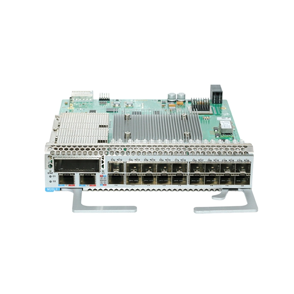
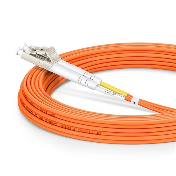
In the field of optical communication, the packaging of optical devices plays a crucial role in the performance and application of optical modules. Common optical device packaging methods include COB (chip-on-board packaging), BOX and coaxial packaging. Today, we will discuss the differences. This article analyzes the requirements of optical transceivers and discusses packaging methods and optical chip types to help readers better understand their design and manufacturing process. They are used in telecom and data communication applications and can be packaged in different ways, including TO, Box, and COB packaging. Regardless of the type of optical module, the. COB packaging means chip-on-board packaging, and the laser chip is adhered to the PCB substrate, which can achieve miniaturization, light weight, high reliability and low cost. The traditional single-channel 10Gb / s or 25Gb / s rate optical module uses SFP package to solder the electrical chip and. The optical transceiver module has three major components, which are opto-electronic devices (TOSA/ROSA), a circuit board with electronic components (PCBA) and optical interfaces (housings) such as LC, SC and MPO. Figure1: Components of an Optical Transceiver The optical transmitting part is.
[PDF]
This article provides a comprehensive framework that governs various aspects of cable tray installations, including the types of cables that are deemed acceptable for use, requirements for grounding and bonding, and stipulations regarding tray fill capacity. en completely installed, without damage either to conductors or structural system use maintain spacing or to keep cables in place when the tray is ect the minimum bend ra-dius for cables as they exit the bottom of the cable tray. A rung spacing of 6 to 9 inches (150 to 230 mm) is preferable when. The use and installation of cable trays is covered by legally enforceable OSHA regulations in 29 CFR 1910. 305(a)(3), or comparable standards promulgated by States operating OSHA-approved State plans. Additionally, it addresses critical. Article Summary: A compliant cable tray installation requires a thorough understanding of NEC Article 392, proper structural support, and precise installation techniques. This guide covers the critical steps, from selecting the right electrical cable tray and performing accurate cable fill. Instrumentation cable trays are critical for organizing and protecting electrical and signal cables in industrial environments. The following pages address the 2014 National Electrical Code® requirements for cable tray systems as well as design solutions from practical experience. The information has been organized for.
[PDF]