Simply put, the output or transmit power (TX Power) is the strength of the signal that's leaving the device. This should fall within a specific range determined by the capabilities of the transmitter. Optical power is the degree of energy that comes from optical signals, which is one of the key parameters of a WDM system. The. In this section, we will learn how to do the following things: Determine the gain of a laser ampli er Find the threshold gain of a cavity Predict the output power of a laser Determine the output mode of the laser Unless otherwise stated, steady state ( d = 0) behavior may dt be assumed. When the signal received is outside of the range, there is a. When it comes to evaluating the performance of an optical transceiver, two key factors come to the fore: Output power (TX Power) and Receiver Sensitivity (RX Sensitivity). An understanding of these concepts is pivotal to establishing an effective and efficient optical network. This comprehensive. As an essential component of optical fiber communication, optical modules are optoelectronic devices that facilitate the conversion between optical and electrical signals during the transmission process. Transmitter power characterizes the average optical power output from the laser under rated conditions, while receiver sensitivity indicates the minimum.
[PDF]
Check the diagnostic information, which shows that the received optical power is low, with a threshold of -3 to -23. 01, currently at -22. Once it exceeds the threshold, an alarm will be triggered. Troubleshoot the link, and if the link is normal, replace the optical. Run the display interface transceiver verbose command in the user view to check whether the transmit optical power (Tx Power) of the interface is within the allowed range. If yes, collect alarm, log, and configuration information, and contact technical support personnel. If the optical module is. An optical module was faulty. Cause 2: Output Optical Power Too High. Services on the optical module may be affected, which may cause bit errors, error packets, or even service interruption. During use, reading optical module information helps understand its real-time operating status, enabling faster troubleshooting of link abnormalities. The following uses the. The International Photonics & Electronics Committee (IPEC) is an international standards organization that is committed to developing open optoelectronic standards and delivering strategic roadmap reports. IPEC focuses on standardizing solutions in optical chips, optical/electrical components, and. The optical module on the port generates an alarm. Often referred as I²C, I2C, IIC (Inter-Integrated Circuit), MDIO (Management Data Input/Output) or CMIS (Common Management Interface Specification), these serial bus.
[PDF]
Absolute optical power calibration of optical power meters, radiometers and photodiodes: From 350 to 1650 nm in 5 nm steps, power range +10 to -60 dBm / 10 mW to 1 nW, with least uncertainty of 0.06 dB.
[PDF]
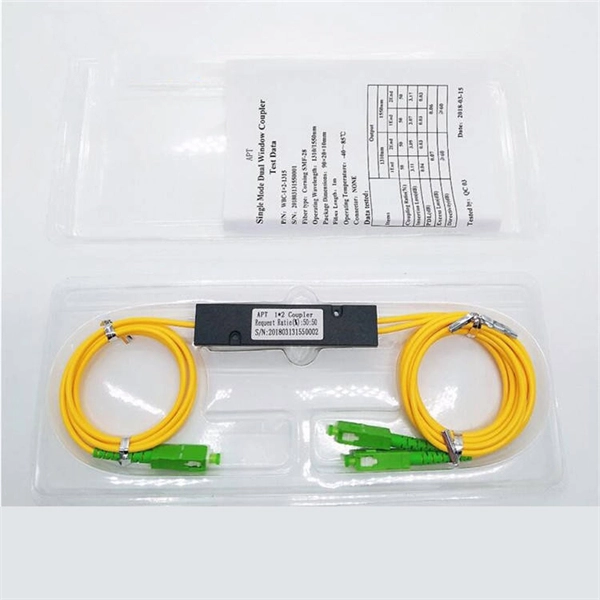
FBT splitters are more sensitive to fiber bending and environmental expansion, particularly under uneven thermal conditions. A beam splitter or beamsplitter is an optical device that splits a beam of light into a transmitted and a reflected beam. It is a crucial part of many optical experimental and measurement systems, such as interferometers, also finding widespread application in fibre optic telecommunications. a laser beam) into two (or sometimes more) beams, which may or may not have the same optical power (radiant flux). Different types of beam splitters exist, as described in the. Fiber optic splitters distribute optical power from one input fiber to multiple output fibers through either fused biconical taper (FBT) coupling or planar lightwave circuit (PLC) waveguide structures. Their performance depends on optical symmetry, waveguide integrity, and mechanical stability of. : The invention provides a light generating system (1000) comprising a first light generating device (110), a second light generating device (120), a luminescent material (200), a diffuser assembly (700), optical elements (500) comprising a first redirection optical element (1510), and a light exit. When splitting one incident light beam into two separate beams, beamsplitters are applied. Depending on the beam split based on intensity, wavelength, or polarization, its level of optical power on beam penetration differ. Just to mention few, these beamsplitter components are commonly required for.
[PDF]
Use the command display transceiver to view the optical module information of all optical ports, and use the command display transceiver interface interface-type interface-number to view the optical module information of a specific optical port. Related Information Video Identify a Huawei-Certified Optical Module Run the display transceiver [ interface interface-type interface-number | slot slot-id ] [ verbose ]. Here is an example on how to query or display optical power of an interface in a Huawei Router. This is tested using NetEngine40E Universal Service Router or NE40E running version 8. The specific viewing information is as follows:. Optical modules are widely used in switches, network interface cards (NICs), routers, and other communication devices. During use, reading optical module information helps understand its real-time operating status, enabling faster troubleshooting of link abnormalities. Transceiver Type : 1000 _BASE_SX_SFP Connector Type :LC Wavelength(nm) : 850 Transfer Distance(m) : 300 (50 um), 150. We want to troubleshoot transceiver on Huawei router, Huawei switch, Huawei systems. 1 Show details, warning etc. from transceivers Check “Alarm information” section for warnings, LOS Alarm means no inbound signal, execute display this to check shutdown mode, execute undo shutdown if necessary.
[PDF]
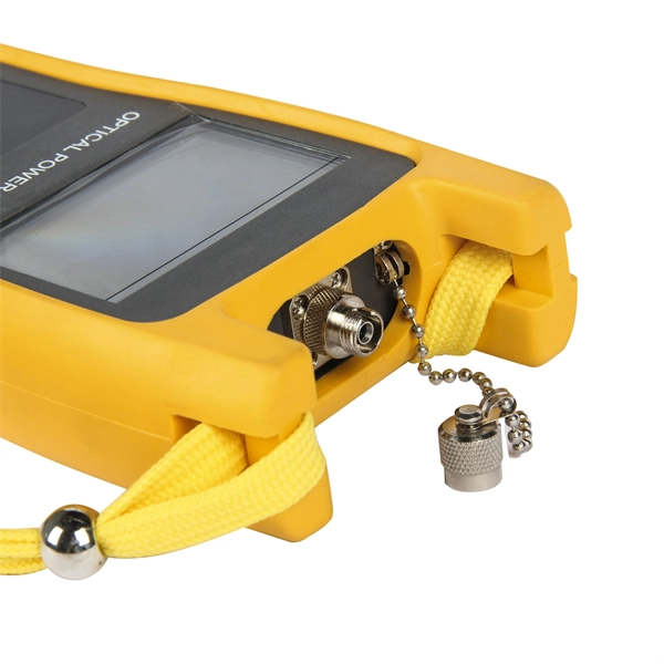
An optical power meter is an electronic device that measures the power of an optical signal. It helps engineers verify the performance of optical fiber systems, ensuring that the signal strength meets requirements, and is an essential tool for communication network maintenance and. An optical power meter (OPM) is a device used to measure the power in an optical signal. Other general purpose light power measuring devices are usually called radiometers, photometers, laser power meters (can be. An optical power meter (OPM) measures the power levels of light signals in devices that transmit data or power using light. The term "optical power meter" may sound generic, but in popular usage, it specifically implies a fiber optic power meter. For light power measurements outside the field of. Optical Power Meters (OPMs) are crucial instruments in the field of optical sensors and fiber optic communications. It provides an expert-curated supplier directory, buyer-focused technical background information, and structured selection criteria to support professional procurement decisions. It measures optical power directly, and it is also used in loss testing when paired with a stable light source.
[PDF]
Optical modules typically have an electrical interface on the side that connects to the inside of the system and an optical interface on the side that connects to the outside world through a fiber optic cable. An optical module is a typically hot-pluggable optical transceiver used in high-bandwidth data communications applications. Composition of Optical Modules The optical module, known as Optical Transceiver in. Optical modules are electronic devices that convert electrical signals into optical signals for transmitting data over an optical fiber. These modules typically consist of a transmitter, which converts electrical signals into a light signal, and a receiver, which converts the received signal back. The optical module serves as a crucial component in optical fiber communication systems, operating at the physical layer, which is the lowest layer in the OSI model. Operating at the physical layer of the OSI model, optical modules are core devices in optical. SFP modules perform three primary functions in a network: For optical modules, the SFP contains a TOSA (Transmit Optical Subassembly) and ROSA (Receive Optical Subassembly) to handle the fiber signal. For copper SFP modules (RJ-45), the module integrates the necessary PHY and magnetics to convert.
[PDF]
At its core, a fiber optic splitter relies on the principles of light reflection, refraction, and waveguiding to divide signals. Its design varies by type, but the underlying mechanism involves manipulating light to distribute its power across multiple output ports. A fiber optic splitter is a passive optical component that divides a single incoming optical signal into two or more outgoing signals, or combines multiple incoming signals into one. Their ability to efficiently manage optical signals makes them indispensable in various. This guide will demystify this pivotal passive device, exploring its types, working principles, and how it seamlessly integrates with optical transceivers to bring high-speed internet to your doorstep. 📄 What is an Optical Splitter? An Optical Splitter, also known as a beam splitter, is a passive. Fiber optic splitter is a passive optical device that includes multiple input and output ends. This principle allows a single input light beam to be split into N output light beams. The splitting can be achieved through two main methods: parallel beam splitting and beam divergence splitting. For example, an optical splitter.
[PDF]
A Thin-Film Filter (TFF) is an optical device that uses multiple layers of dielectric coatings deposited on a substrate to selectively transmit or reflect specific wavelengths of light. It is a fundamental component in modern optical communication systems. The Z-Block is a core optical component used in wavelength division multiplexing/demultiplexing (WDM) systems. Structurally, it is typically composed of several integrated optical elements, including collimating lenses, rhomboid prisms, and specially designed optical mirrors. TFFs are widely used as. The Process Technology of Optical Coating: Applications of TFF in Optical Communication Optical coating technology has revolutionized the way we enhance the performance and durability of optical devices, particularly in optical communication systems. As the demand for high-speed internet and. WDM (Wavelength Division Multiplexing) is a technology that expands the optical fiber transmission bandwidth and improves network transmission capacity by transmitting multiple optical signals of different wavelengths in the optical fiber. TFF (thin film filter) and AWG (arrayed waveguide grating). A thin film resonant cavity filter (TFF) is a Fabry-perot A cavity is formed by using multiple reflective dielectric thin film layers. The TFF works as bandpass filter, passing through specific wavelength and reflecting all other wavelengths. The cavity length decides the passing wavelength.
[PDF]
A WDM system uses a multiplexer at the transmitter to join the several signals together and a demultiplexer at the receiver to split them apart. With the right type of fiber, it is possible to have a device that does both simultaneously and can function as an optical add-drop. In fiber-optic communications, wavelength-division multiplexing (WDM) is a technology which multiplexes a number of optical carrier signals onto a single optical fiber by using different wavelengths (i., colors) of laser light. This technique enables bidirectional communications over a. WDM is a fiber optic transmission technique that leverages multiple light wavelengths to transmit data efficiently over a single medium. WDM technology employs different optical wavelengths, or colors, of laser light to multiplex several optical carrier signals onto a solitary optical fiber. Each. There are a lot of people who don't understand the difference between WDM and optical splitter. This allows multiple channels of data to be transmitted simultaneously. WDM technologies allow organizations to place equipment at either end of a fiber pair and combine multiple wavelength channels on a single fiber pair instead of using multiple separate fibers pairs for every separate service. The article explains the fundamental principle and its.
[PDF]
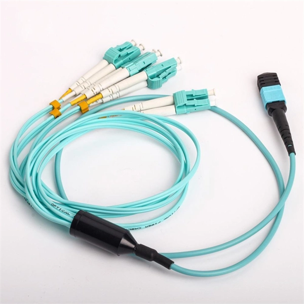
This guide provides a fully updated and industry-ready overview of LC fiber optics, explaining the origin and design of LC connectors, their key features, and the complete ecosystem of LC-based products used in modern networking. LC fiber connectors, as the most well-known representative of SFF (Small Form Factor) connector, are widely adopted in today's LAN and data center cabling. You may find LC connector has a strong family which includes but not limited to LC optical fiber connectors, LC fiber patch cables, LC fiber. Data centers will keep dominating optical module demand as AI and cloud drive revenue growth through 2030. Optical module demand is being pulled in two directions at once, faster bandwidth for dense networks and tighter constraints on power, security, and lead times. With global R&D projected to. LightCounting has proudly served our industry for 22 years with reports and services designed to help executives plan and run their businesses. We support decision-making based on our data, expert analysis and trusted forecasts. It covers LC connectors, LC patch cables, uniboot designs, armored. Optical Module Package Market was valued at 8942 million in 2024 and is projected to reach US$ 20220 million by 2032, at a CAGR of 12. With the surge in data traffic and the increasing demand for higher bandwidth, 100G optical modules have gained immense traction. These modules facilitate high-speed.
[PDF]
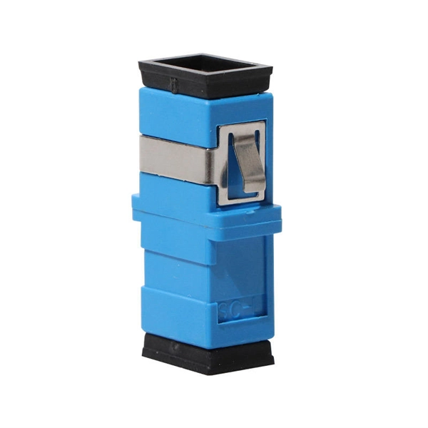
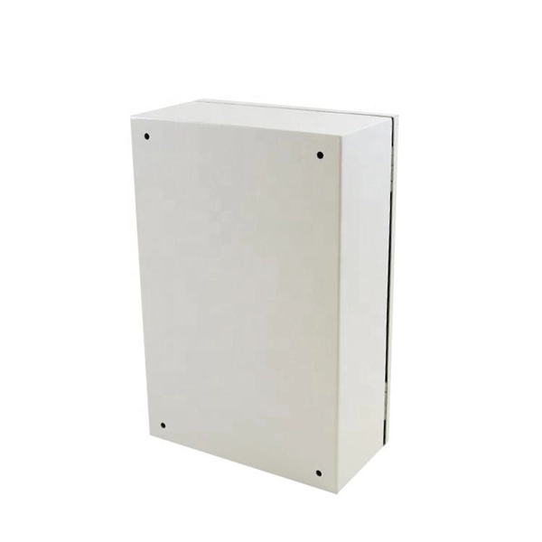
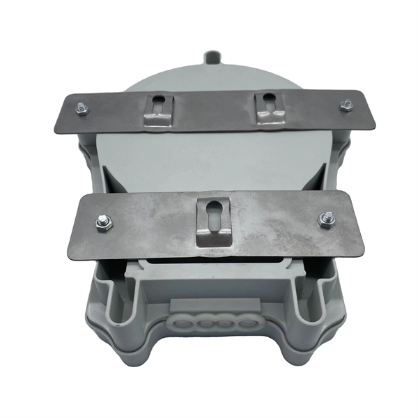
Through the adapter in the distribution box, the optical signal is led out by the optical jumper to realize the optical wiring function. An optical cable consists of three primary parts: the core, the cladding, and the protective sheath. The core is at the center of the optical cable and serves as the pathway for transmitting light signals. Surrounding the core is the cladding, which has a lower refractive index than the core. In the complex architecture of fiber optic networks, the Optical Distribution Frame (ODF) serves as the linchpin for organizing, protecting, and distributing optical signals. Whether in data centers, telecom central offices, or enterprise network rooms, ODFs enable efficient fiber management. The optical fiber distribution box is to protect the connection point where the optical cable is connected to the user end, so that the optical cable access point is stable, dustproof and waterproof. What is a fiber distribution box? 2. The. A fiber distribution box (FDB) functions as a central hub in fiber optic networks where the main cable is split into multiple individual fibers for distribution to end users. These boxes protect sensitive fiber connections from environmental factors while providing an organized framework for.
[PDF]
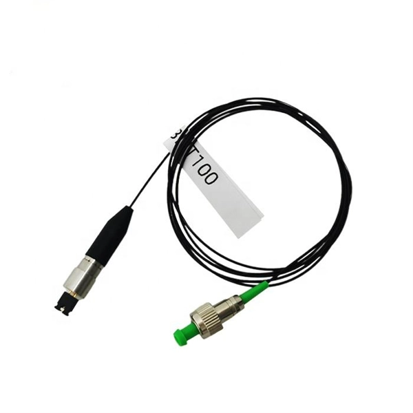
Short answer: Usually yes, you use them in pairs, but the “pair” can be a media converter on one end and a fiber switch (or SFP in a switch) on the other, as long as both sides speak the same speed, wavelength, and optical mode. Mixing single-mode and multi-mode transceivers creates major optical and hardware problems. This leads to unreliable network performance. Here's why: Light source & beam profile: SM lasers are narrow and Coherent; they couple efficiently into a 9 µm core. MM VCSELs/LEDs produce a broader beam. Single-mode optical modules are best for long distances and fast speeds. They use a thin fiber core. Picking the right optical module depends on your network needs. The sfp transceiver single mode typically utilizes laser diodes as the light source and operate at wavelengths of 1310nm or 1550nm. The key is opposite directions use opposite wavelengths, so A must face B—AA or BB will not work. Other BiDi pairs exist (e. Single-mode fibers support a wide band and large transmission capacity, and are used for long-distance. o In optical modules, "core" refers to the light-transmitting channel in the fiber. A 1-core module uses a single fiber core for data transmission, while a 2-core module uses two cores. o Think of a highway. A 1-core fiber is like a single-lane road—only one car (or data signal) can travel at a.
[PDF]
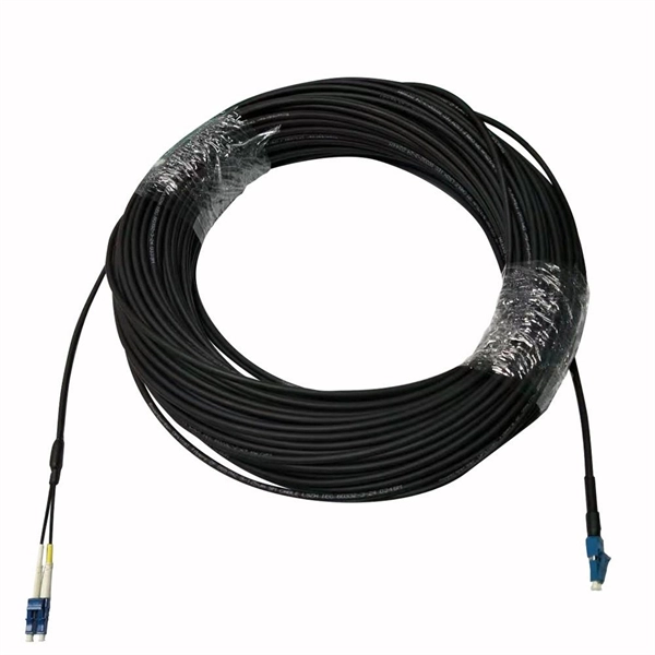
Yes, fiber cables can be bent during installation, which proves particularly useful when you pull cables into position rather than using blown installation methods. Blown fiber installation uses air pressure to propel cables through conduits, minimizing bending stresses. Fiber optic cables are designed to withstand some bending, but excessive bends can physically damage the glass fiber or cause significant signal loss. That's why every fiber cable has a minimum bend radius specification provided by the manufacturer. The minimum bend radius defines the smallest. All fiber optic cables have specifications that must not be exceeded during installation to prevent irreparable damage to the cable. Installers must understand these specifications and know how to install cables without. The bend radius of fiber cables is critical for maintaining high performance and longevity. A practical single-mode fiber option for compact routing, dense fiber management, FTTH access, and reel-based systems such as drone fiber and FPV fiber tether where bend-loss control matters in real installation and maintenance conditions. The tighter the bend, the smaller the radius. The minimum bend. Astel 4 Core Siamese model has 2 x 2 Fiber cables joined in the center by steel messenger. Its main advanctage is that a single cable can be used for 2 independent telecom operators. The optical fiber is made of high pure silica and.
[PDF]
Optical isolators protect sensitive sources by blocking back-reflected light that could cause instability or damage. Optical circulators, meanwhile, manage directional routing through multiple ports, enabling duplex communication, optical path control, and compact system. of low-loss non-reciprocal fiber-based devices. Here, we present a solution to this issue by realizing low-loss (0. 81 dB), broadband (at least 50 GHz bandwidth) and high-extinction (up to 27 dB) circulators, based on Mach-Zehnder interfer meters including so-called fiber null-couplers. The latter. The ABSTRACT optical circulator is one of the key devices in the optical add-drop modules (OADMs) used in wavelength-division multiplexing (WDM) technology, which finds applications in large-capacity long-haul telecommunications systems. PM circulators. Faraday circulators (or less specifically optical circulators) are a kind of non-reciprocal optical devices. They are technically related to Faraday isolators, and on a broader scale similar to electronic circulators. Typically, a circulator has three or four optical ports (inputs / outputs). GKER Photonics Co. is really leading the charge in this area, providing key Optical Components that boost the reliability and performance of things like industrial fiber lasers and optical networks, not to mention data centers. If global suppliers take the time to understand what really.
[PDF]