Absolute optical power calibration of optical power meters, radiometers and photodiodes: From 350 to 1650 nm in 5 nm steps, power range +10 to -60 dBm / 10 mW to 1 nW, with least uncertainty of 0.06 dB.
[PDF]
It performs error detection and alarm monitoring, serving as an essential tool for bit error testing in R&D and production of optical modules/ devices. Bit Error Ratio Tester is an instrument used to test and analyze bit error ratio in digital transmission systems, fiber optic communication systems, and digital microwave communication systems. Dimension Technology's BERT800 bit error tester series offers a comprehensive solution for testing and verifying high-speed optical transceiver modules. OPTELLENT is a provider of broadband test and measurement solutions for communications. The Company's test & measurement solutions are used in product development, manufacturing. As transmission rates continue to accelerate, accurately measuring bit error rates in optical modules is crucial to ensure reliable performance. There are three interchangeable slot boards which include QSFP, SFP+ and SFP ports separately. QSFP, SFP+ and SFP ports follow QSFP MSA, SFP+ MSA and SFP MSA. The user interface allows you to individually monitor bit error rate, error count and timer by connecting to PC via USB cable. In high-speed digital communication systems, even the smallest bit-level error can compromise performance, reduce efficiency, or lead to costly rework.
[PDF]
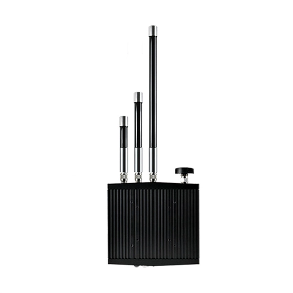
An AMR unit can be retrofitted onto an existing meter to automatically ping the meter and get a current reading. The meter data is transferred to a database where it can be monitored, analysed and used to bill customers based on actual consumption. An AMR (Automated Meter Reading) meter collects data from your gas, electricity, or water meter and transmits it to a central platform in real time. It eliminates manual readings and gives you instant access to consumption data. We offer industry-leading SmartPoint ® modules that read and store. With our Automated Meter Reading (AMR) systems, you can automatically capture water consumption and status data from water meters just by walking or driving by with mobile reading software that collects data and synchronizes with BEACON ® SaaS hosted software. One Comprehensive. The meter communicates to its collection point using 900 MHz mesh network topology. Automatic Meter Reading (AMR) Systems are technological solutions that enable the remote and automated reading of meter data for energy sources such as electricity. We support you with a powerful, modular radio technology that delivers high-frequency energy data - with stable transmission, long range and low maintenance. As a water and energy provider you need a flexible solution for remotely reading consumption meters that is tailored to your precise needs.
[PDF]
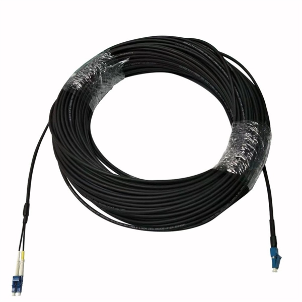
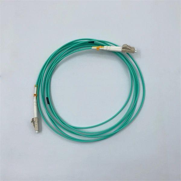
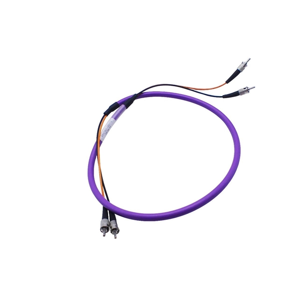
Typical rates range from $0. 00 per ft depending on terrain, access, and required precision for termination. Basic — 1,000 ft single-mode run indoors with minimal termination: Cable $0. 00/ft, Permits $150, Accessories $100. Total ≈ $2,650–$3,100. 🔥Buy Fiber Cables products online from DanounTech the best tech store📱 in Lebanon🇱🇧 | find low prices everyday, and enjoy fast delivery🚚. DanounTech | LEBANON. Fiber optic solutions (drawers, panels, connectors. ) | Fibre optic cables | !. 50-meter, 2-core single-mode fiber optic cable with APC (Angled Physical Contact) connectors, providing low-loss, low-reflection performance for high-speed data transmission. Ideal for FTTH, telecom, and network infrastructure requiring reliable duplex connectivity. Each cable features advanced fiber optic technology to deliver superior performance, low latency, and high bandwidth. Anixter is your source for Indoor/Outdoor Fiber Optic Cable products. olx Lebanon offers online local classified ads for Fiber Optic. Post your classified ad in various categories like mobiles, tablets, cars, bikes, laptops, electronics, birds, houses, furniture, clothes, dresses for sale in Lebanon.
[PDF]
Engineered for FTTH network systems, this all-in-one outdoor optical distribution box seamlessly integrates splicing, splitting, distribution, and cable storage within a single, weatherproof enclosure. The 8 core optical branching box is produced and developed by our company completely, and the product's performance in accordance with the industry standard requirements. It's mainly used in FTTX access system terminal link. The box made of high strength PC plastic alloy injection molding, which. Deploy a reliable and robust fiber access point with the JUNPU JP-I1-8OA outdoor fiber distribution box. Maximum capacity: 8 SC simplex, 8 LC duplex. The 8 port Fiber Distribution Box is sturdy in structure, lightweight in size, and easy to install. It can be installed on walls or utility poles, and its waterproof cover ensures maximum moisture protection, ensuring optimal performance in any weather. Price changes against quantity. OEM / ODM is available. Capacity Leading fiber optical box manufacturers & suppliers, provide a range of fiber optic box with different core numbers and support OEM ODM service. The 8-core outdoor fiber optic distribution box provided by OTRANS can effectively improve the stability and security of network transmission, and is widely used in various scenarios such as FTTH networks, CATV networks, local area networks, and telecommunications networks. The fully enclosed.
[PDF]
Drawing on IEC standards and industry research data, it outlines the coverage of mainstream outdoor fiber optic cable types, selection criteria, and best practices for installation, providing a systematic reference for outdoor fiber optic cable deployment. This document serves as a guide for outdoor fiber optic cable selection and installation for professionals in the telecommunications industry. Fiber optic cables for outdoor applications are engineered to withstand the more demanding conditions seen outside, from environmental extremes to mechanical forces. These are the outdoor fiber optic cables you see strung along telephone poles (aerial), installed inside an underground duct, or even. Outdoor fiber optic cables transport data and communications signals over long distances while enduring extreme environments. Whether you're linking buildings, running broadband in rural areas, or building 5G infrastructure, the right cable matters. It affects performance, maintenance, cost, and reliability. Our team will make sure the configuration is tailored to your needs and will provide a detailed quote. Email us using the Request a Quote below, or. hing, conduit and temp rature variations. The Outside Plant cable. These cables are thoroughly tested designed for installation in pathways that are subjected to wide product line offers 6 and 12 fibers per and verified to Telcordia GR 20 a loose tube cables and hybrid design o ts to specific.
[PDF]
Provides accurate and cost-effective testing methods for the optoelectronic signal testingand anomaly simulation of high-speed optical transceiver modules. The OptoBERT™ OPB04X10 is the industry's most compact, cost-effective, easy-to-use 4-channel 10Gbps electrical bit-error-ratio tester (BERT). PBT3058 is a high-performance Bit Error Ratio Tester which can be used for physical layer characterization and consistency test of high-speed serial signal. 6TBASE/CEI-224G standards and also supports PCIe rate testing ranges through extended rate. Transmitter net measurement:. Our portable and stationary provers ensure accuracy and industry compliance for flow meters on a variety of in the field applications. Available in custom configurations and max flow rates, each prover is designed to eliminate the many prover problems of the past including our Unidirectional. In high-speed digital communication systems, even the smallest bit-level error can compromise performance, reduce efficiency, or lead to costly rework. That's why Physical Layer Tech offers precision-engineered Bit Error Rate Testers (BERTs) designed to verify data transmission accuracy and ensure. Whether you are looking for the smallest handheld 100G bit error rate tester in the world for your field job, or perhaps your needs take you into the lab, VIAVI has you covered with our accurate and easy-to-use BERT equipment for any use case. · Use control board and replaceable.
[PDF]
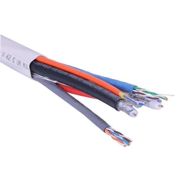
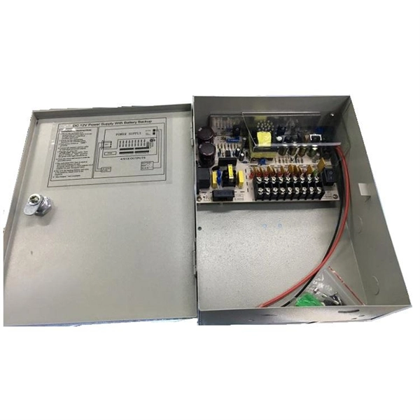
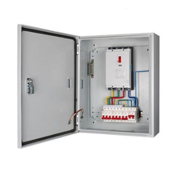
The primary function of a feeder wire is to facilitate bulk power transfer from a central source to a subpanel or a secondary distribution center. An example is the large cable running from the main service panel to a subpanel in a detached garage, basement, or workshop. A main panel and a sub-panel are both important components of an electrical distribution system. It is usually located where the main electrical service enters the building, often on an. Main feeder wires are the arteries of a building's electrical system, designed to safely and efficiently transport a large volume of power from the service entrance to secondary distribution points. They form the backbone of the electrical distribution network, handling the substantial current. An electrical sub panel, also known as a sub distribution board or sub circuit breaker panel, is a smaller secondary panel connected to the main electrical panel in a building. It serves as an extension of the main electrical panel to distribute power to different areas or circuits within a. Distribution board is a safe system designed for house or building that included protective devices, isolator switches, circuit breaker and fuses to safely connect the cables and wires to the sub circuits and final sub circuits including their associated Live (Phase) Neutral and Earth conductors. The distribution box acts as the center of power distribution, distributing electricity to all connected devices.
[PDF]
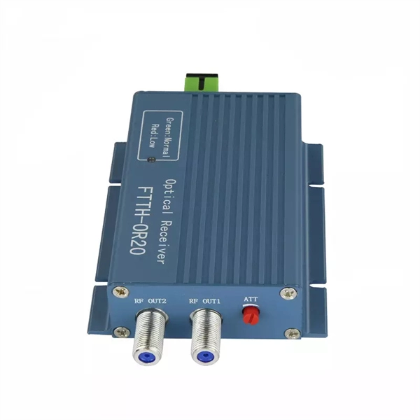
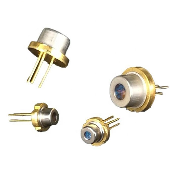
The optical fibre sensors are divided into two categories: thrubeam and reflective. The thrubeam type comprises a transmitter and a receiver. The reflective type, which is a single unit, is available in 3 types: parallel, coaxial, and separate. The fibre optic sensor has an optical fibre connected to a light source to allow for detection in tight spaces or where a small profile is beneficial. The light beam travels through the core by. Fiber optic sensors are prevalent in various applications, from computers and printers to motion detectors. For instance, when a printer or copier door is open, light falls on the sensor, stopping the machine for safety. Fiber optic sensors use light properties to detect and measure physical quantities such as temperature, pressure, and displacement. Depending on the application scenario, different. Functional (all optical fiber type) optical fiber sensor Using optical fibers (or special optical fibers) with sensitivity and detection capabilities for external information as the sensor element, the sensor combines "transmission" and "sensation". During operation, the light source enters the optical modulation region through the incident fiber. The physical quantity to be measured (such as.
[PDF]

This document provides a comprehensive technical overview of the Ring Main Unit (RMU), serving as a reference for power system design, selection, and maintenance. Ring Main Units (RMU s) and Medium Voltage (MV) Switchgear are crucial in MV power distribution. Globally, they each hold about half the market share. MV switchgear handles primary distribution for large industrial facilities and grid infrastructure. RMUs, however, shine in secondary distribution. RMUs are commonly used in secondary distribution systems, particularly in urban areas, industrial complexes, and commercial. Scope of Application: The Ring Main Unit (RMU) is a compact switchgear device used in medium-voltage power distribution systems (typically 10kV–35kV). Some of the key features of the RMU includes SF6 gas insulation, compact and modular construction, integral protection system, fully extendable options. SFA-RM units are designed for supplying reliable energy, protecting electrical equipment in secondary distribution networks up to 17. Their compact design makes them suitable for various network applications such. Loading. Company Introduction:The New Concept Electric Inc. (NCE) was founded in October 2001, with a registered capital of 57 million Yuan. The company now covers an area of 77, 601 square meters (116 acres), and has a building area of 80, 451 square meters.
[PDF]
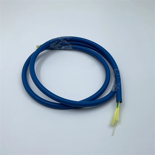
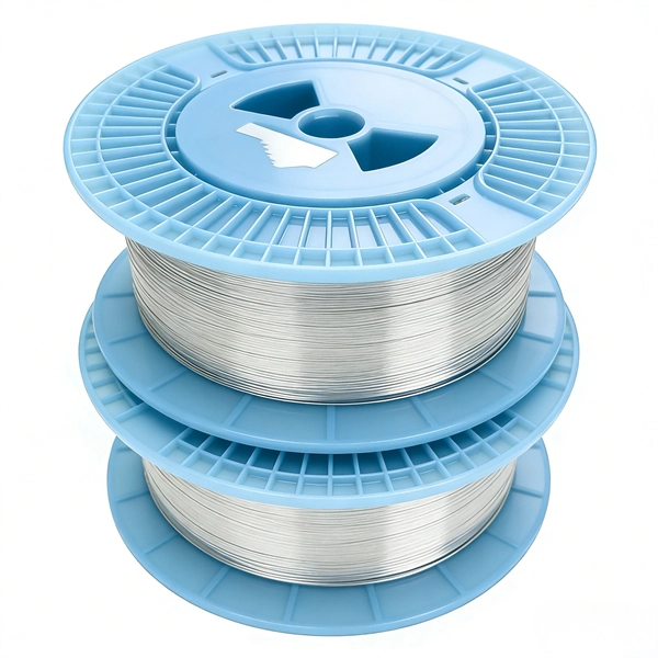
Instead of fusing one fiber at a time, mass fusion splicing can fuse up to all 12 fibers in one ribbon at once. Many of today's cables with high fiber count involve subunits of 12 fibers each that can be quickly ribbonized. Fiber optic joints or terminations are made two ways: 1) splices which create a permanent joint between the two fibers or 2) connectors that mate two fibers to create a temporary joint and/or connect the fiber to a piece of network gear. Either joining method must have three primary characteristics. Fiber optic splicing is the process of seamlessly joining two single Splicing has a lower optical loss and back-reflection than other terminations, making it the ideal choice for maintaining signal integrity and reliability in fiber optic networks. There are numerous use cases for fiber optic splicing. Through splicing, fiber optic technicians can extend the length of the fiber to make it long enough for use in a required cable run. As. To begin, the standard definition of splicing in optical fiber is joining two fiber optic cables together. The other, more common, method of joining fibers is called termination or connectorization. Splicing is most commonly used in the field but has application in cable assembly houses.
[PDF]
Optical modulators are used in optical communication systems to encode data onto light waves for transmission through optical fibers. The modulator encodes the data onto the light wave by modifying its amplitude, phase, or frequency. 📦 For purchasing, use the RP Photonics Buyer's Guide for optical modulators. It provides an expert-curated supplier directory, buyer-focused technical background information, and structured selection criteria to support professional procurement decisions. What are Optical Modulators? An optical. Optical modulators are devices that modify the properties of light, such as its amplitude, phase, frequency, or polarization, in response to an external signal. These devices play a crucial role in modern optics and photonics, enabling the manipulation of light for various applications. The beam may be carried over free space, or propagated through an optical waveguide (optical fibre). It acts as the “translator” between the electronic and photonic worlds. They enable the modification of optical wave characteristics such as the intensity, phase, polar-ization, and frequency of light signals. There are basically two types of modulators: bulk and integrated-optic.
[PDF]
An optical power meter is an electronic device that measures the power of an optical signal. It helps engineers verify the performance of optical fiber systems, ensuring that the signal strength meets requirements, and is an essential tool for communication network maintenance and. An optical power meter (OPM) is a device used to measure the power in an optical signal. Other general purpose light power measuring devices are usually called radiometers, photometers, laser power meters (can be. An optical power meter (OPM) measures the power levels of light signals in devices that transmit data or power using light. The term "optical power meter" may sound generic, but in popular usage, it specifically implies a fiber optic power meter. For light power measurements outside the field of. Optical Power Meters (OPMs) are crucial instruments in the field of optical sensors and fiber optic communications. It provides an expert-curated supplier directory, buyer-focused technical background information, and structured selection criteria to support professional procurement decisions. It measures optical power directly, and it is also used in loss testing when paired with a stable light source.
[PDF]
Typical project ranges for fiber optic cable per meter span from a low of roughly $0. 65 to a high around $5. 00, depending on type, protection, and installation needs. The majority of projects cluster in the $1. 60 per meter range for standard indoor runs with simple. Fiber optic cable cost per meter varies by type (single‑mode vs multi‑mode), durability, and installation conditions. The main price drivers include cable grade, jacket material, pull tension, connectorization, and any required conduit or protection. The following coverage gives a practical price. Fiber-optic cable materials typically cost $1 to $6 per linear foot, depending on fiber count and cable type. Commercial building installations with 100-200 network drops generally range from $15,000 to $30,000. The type of fiber optic cable selected based on your requirements, length of installation, and number of fiber. Getting accurate cost estimates is crucial for winning fiber installation bids. Smart contractors know that underground vs aerial installation pricing varies wildly based on location and project conditions. We'll show actual costs for.
[PDF]
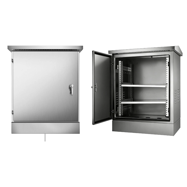
This combination of robust protection, cooling efficiency, and adaptability makes the 16U 19 Outdoor Network Cabinet with AC Unit IP 66 NEMA Enclosure the ultimate solution for safeguarding your network equipment in any outdoor or industrial setting. Our outdoor cabinets withstand harsh weather conditions and adverse industrial environments. We will be happy to customize outdoor cabinets to your. Why cool an electrical panel? The cooling of electrical panels or cabinets is essential in any application to ensure the proper functioning of internal components and production processes, preventing and avoiding production and/or distribution downtime. When managing a network in an outdoor. Delvalle thermal management, provide effective and energy efficient cooling and heating to meet the unique needs of your application. Our climate controlled boxes and enclosures feature built-in air conditioners, heaters and thermostats and are ideal for mounting electrical and electronic equipment. Our vast selection of cabinets, thermal management, racks, enclosures for data centers, telecommunications equipment rooms, and enterprise cabling applications help optimize space, reduce energy consumption, and enhance network reliability. The use of reliable telecom infrastructures has grown, thus increasing the difficulties of heat management in small and modern technology areas. This detailed guide will consider different cooling techniques.
[PDF]