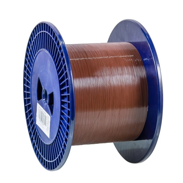
This fiber, known as non-zero dispersion-shifted fiber, has a small amount of dispersion in the 1550 nm operating window. This fiber type is widely used for transmitting multiple high-speed data channels across a single fiber in the 1550 nm range. Featuring a high-performance core design, these fibers deliver exceptional beam quality and low splice loss. The NuCOAT fluoroacrylate coating ensures superior environmental durability. That value determines whether the module is designed for multimode fiber (MMF) or single-mode fiber (SMF), how much attenuation the signal will experience, how dispersion behaves over distance, and whether optical amplification or DWDM systems are possible. Choosing the wrong wavelength can result. The F-SMF-28 Single-Mode Fiber from Corning (SMF-28e+) is all-glass and supports single-mode light propagation for a 1310/1550 nm operating wavelength. Optimized for access and metro networks, this fiber is compliant with Recommendation ITU-T G. Patch cables that incorporate these fibers are available from stock, see. This document outlines the specifications for a single-mode optical fiber and cable designed for use around the 1310 nm zero-dispersion wavelength, suitable for both the 1310 nm and 1550 nm regions, and compatible with analogue and digital transmission. It can be used in all cable constructions, including loose tube, tight buffered, ribbon, and.
[PDF]
Check the diagnostic information, which shows that the received optical power is low, with a threshold of -3 to -23. 01, currently at -22. Once it exceeds the threshold, an alarm will be triggered. Troubleshoot the link, and if the link is normal, replace the optical. Run the display interface transceiver verbose command in the user view to check whether the transmit optical power (Tx Power) of the interface is within the allowed range. If yes, collect alarm, log, and configuration information, and contact technical support personnel. If the optical module is. An optical module was faulty. Cause 2: Output Optical Power Too High. Services on the optical module may be affected, which may cause bit errors, error packets, or even service interruption. During use, reading optical module information helps understand its real-time operating status, enabling faster troubleshooting of link abnormalities. The following uses the. The International Photonics & Electronics Committee (IPEC) is an international standards organization that is committed to developing open optoelectronic standards and delivering strategic roadmap reports. IPEC focuses on standardizing solutions in optical chips, optical/electrical components, and. The optical module on the port generates an alarm. Often referred as I²C, I2C, IIC (Inter-Integrated Circuit), MDIO (Management Data Input/Output) or CMIS (Common Management Interface Specification), these serial bus.
[PDF]
This report studies the global Optical Module PCB Board production, demand, key manufacturers, and key regions. Optical Module PCB Board by Application (Optical Receiving Module, Optical Transmitting Module, Optical Transceiver Module, Optical Forwarding Module), by Types (Single-layer PCB, Double-layer PCB, Multi-layer PCB), by North America (United States, Canada, Mexico), by South America (Brazil. Dongshan Precision plans to acquire Taiwan's Source Photonics for up to $850 million to expand its optical communications business. The deal, which aims to integrate Source Photonics' vertically integrated operations and high-speed optical module capabilities, is pending approval from Taiwan's. The Optical Module PCB Board market is experiencing significant growth, driven by the increasing demand for high-speed data transmission in various industries, including telecommunications, data centers, and consumer electronics. These printed circuit boards (PCBs) play a vital role in connecting. The global Optical Module PCB Board market size was US$ million in 2024 and is forecast to a readjusted size of US$ million by 2031 with a CAGR of %during the forecast period 2025-2031. The Optical Module PCB Board Market is expected to grow from 2,490 USD Million in 2025 to 5. 8 USD Billion by 2035. This report is a.
[PDF]
This market research report provides a comprehensive analysis of the current size of the Optical Modules industry. It leverages historical data to extract key industry insights, tracing the market's evolution over time. Optical Module Package Market was valued at 8942 million in 2024 and is projected to reach US$ 20220 million by 2032, at a CAGR of 12. Quotas are established by legislation, Presidential Proclamations or Executive Orders. Quotas are announced in specific legislation or may be provided for. Segments - by Product Type (Transceivers, Cables, Amplifiers, Splitters, and Others), Application (Data Centers, Telecommunications, Enterprises, and Others), Data Rate (10G, 25G, 40G, 100G, 400G, and Others), Form Factor (SFP, QSFP, CFP, and Others), and Region (Asia Pacific, North America, Latin. The global market for Optical Modules was estimated to be worth US$ 17590 million in 2024 and is forecast to a readjusted size of US$ 56786 million by 2031 with a CAGR of 15. 8% during the forecast period 2025-2031. The potential shifts in the 2025 U. QSFP-DD (Quad Small Form-factor Pluggable-Double Density) Optical Module: Double-density four-channel small pluggable packaged optical.
[PDF]
The transceiver is available as a mini-GBIC form factor, making it ideal for environments that require many fiber connections by taking up less space in your cabinet and/or computer room. Compatibility in your network is everything, and the Intellinet SFP Transceiver Module delivers. Use it with any Intellinet SFP equipped network switch or any other MSA-compliant, SFP-enabled switch. And since the Intellinet SFP transceiver module is set to broadcast the vendor on GLC-LH-SM, compatibility to your Cisco gear is provided. No need to power down your LAN switch in order to install or remove the transceiver. This makes it very convenient and easy for you to make adjustments to your network that allow your business to keep pace with the changing demands of the market.
[PDF]
The Optical Module Chip Base is a critical packaging platform designed to support core components such as laser chips, detector chips, and driver chips in high-speed optical communication modules. The primary optical communication devices used are optical modules and optical chips, which are essential for high-speed data transfer and network interconnection. It serves as a bridge between the chip and external optical fibers or circuit systems, ensuring. In the backbone of the global digital infrastructure, optical modules are the unsung heroes, converting electrical signals into pulses of light and back again, enabling the high-speed data transmission that powers the internet, cloud computing, and telecommunications. At the heart of every advanced. An optical module is a device that converts electrical signals into optical signals and vice versa. Among various optical module form factors, SFP (Small Form-Factor Pluggable).
[PDF]
Your eyes contain two types of light-sensing cells: rods and cones. Rods detect low-light vision and motion, while cones handle color vision and detail in bright light. Damage to either can lead to vision problems like night blindness or color blindness. Protecting your eyes with proper nutrition. Personnel Safety. Optical Touch Buttons. Self-contained Sensors. Each technology has unique strengths and weaknesses, so the requirements of the application itself will determine what technology should be used. This article is focused on photoelectric sensors and defines what they are, their adv ors are readily present. Quality Control: They can detect defects, ensure proper product placement, and verify the presence of components. Safety: They can be used to create safety barriers, preventing machinery from operating when a person or object is in a hazardous zone. In this section, we explore the geometric optics of the eye. Early thinkers had a wide array of theories regarding vision. Euclid and Ptolemy believed that the eyes emitted rays of light;. Understanding the eye involves examining how its individual parts contribute to the overall function. Vision begins as light enters the eye through the cornea, a transparent, dome-shaped outer.
[PDF]
Delta's modular datacenter solution offers a datacenter environment that provides safe equipment operations within the racks, and supports the development and standardizing of micro datacenters that fit into racks. Delta InfraSuite is a new generation, highly integrated modular datacenter solution. It uses racks as the datacenter carrier and fully integrates all sub-systems including UPSs, cooling, power distribution, lightning protection, fire control (optional), wiring, airflow management, intelligent. Rack-Level, 3. 5kW Edge Infrastructure with Integrated Backup Cooling for Remote and Space-Constrained Environments What Makes a Micro Data Center the Ideal Solution? A micro data center is a compact, self-contained infrastructure solution that integrates compute resources, storage, power. Delta InfraSuite is a new generation, highly integrated modular datacenter solution. Its mission statement, “To provide innovative, clean and energy-efficient solutions for a better tomorrow,” focuses on addressing key environmental ssues such as global climate change. As an energy-saving solutions provider with core competencies in power.
[PDF]
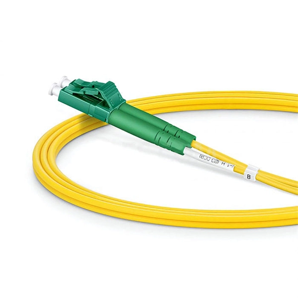
SFP28 (Small Form-Factor Pluggable 28) is an enhanced version of SFP+, designed to support 25Gb/s data rate transmission while maintaining the same package type. SFP28 is backward compatible with SFP+. However, compatibility can vary based on the specific SFP models, networking equipment, and vendors involved. It's advisable to consult your vendor for precise information regarding compatibility. ①. This article helps network engineers and field techs confirm SFP backward compatibility when mixing SFP, SFP+, and SFP28 optics in the same switching ecosystem. You will get concrete specs, a decision checklist, and troubleshooting patterns that show up in daily operations. ① Plug a 1000BASE-SX SFP transceiver into the SFP port on a gigabit. Common form factors are SFP (1 G), SFP+ (10 G), SFP28 (25 G), QSFP+ (40 G) and QSFP28 (100 G). The question we answer below is simple: “Which of these can I mix and match without killing the link? What “compatibility” really means? All reputable transceivers follow the Multi-Source Agreement (MSA). SFP28 optical transceiver modules provide a transmission rate of 25 Gbps and use LC connectors. 25G SR/eSR are not supported for use. Q: Can I use an SFP transceiver in SFP28 ports? A: Yes, you can. However, it's important to note that while SFP transceivers and cables can be plugged into SFP28 ports, they won't support the higher 25Gb/s data rate of the SFP28.
[PDF]
As illustrated in typical SFP internal structure diagrams, the module's core components include an optical transmitter assembly (TOSA), laser driver, optical receiver assembly (ROSA)—some high-sensitivity modules (like L16. 2) use APD receivers, which require an additional booster. As a key element in optical communication systems, optical transceivers serve as media between network devices to transmit and receive data. There has been lots of articles and guides on transceiver modules in the perspective of the package type while only a few of them cover the internal elements. Optical modules are devices used to connect network devices, transmit and receive data between network devices, and can be used to convert optical and electrical signals. The optical module is a very important component in an optical communication system. When you remove the metal housing of the optical transceiver, you will find that the internal components are connected to each other. The following section will focus on. In the era of 5G, AI, and high-speed data centers, optical modules serve as the core bridge for converting electrical signals to optical signals (and vice versa), enabling fast, reliable data transmission across networks. Among various optical module form factors, SFP (Small Form-Factor Pluggable). The optical transceiver module is mainly composed of three parts: housing, optical device and integrated circuit board. The following section will focus on.
[PDF]
Huawei OLT Comparison: MA5600T vs MA5800 vs EA5800. This guide explains the architectural differences, PON technologies (GPON, XGS-PON), and helps you choose the right OLT for FTTx networks. MA5603T is multi service based while MA5683T is just OLT, MA5603T can support service like ADSL, VDSL, GPON etc, while MA5683T only supports GPON, P2P etc, but their hardware and configuration command is the same. MA5683T vs MA5680T? The only difference is capacity, MA5683T max support 6 service. Hi, This is ISP-Home. com, we excel in delivering high-performance fiber optical products, connecting you to a world of precision and reliability. As optical fiber access nodes keep moving closer to end users, OLTs are closer to end users. Deployment scenarios are complex and diversified. In this case, network needs OLTs with small volume and low density. The MA5801 series OLT is a compact and. When selecting a Huawei OLT (Optical Line Terminal), prioritize models that support your required number of subscribers, offer scalable GPON or XGS-PON technology, and integrate seamlessly with existing Huawei ONTs. For most mid-sized service providers, the MA5600T or MA5800-X17 provides the best. OLT Series: Access product manuals, HedEx documents, product images and visio stencils. The MA5800 is the industry's first smart aggregation OLT with a distributed architecture. It is positioned as the next-generation OLT for NG-PON.
[PDF]
Optical modules typically have an electrical interface on the side that connects to the inside of the system and an optical interface on the side that connects to the outside world through a fiber optic cable. An optical module is a typically hot-pluggable optical transceiver used in high-bandwidth data communications applications. Composition of Optical Modules The optical module, known as Optical Transceiver in. The optical module serves as a crucial component in optical fiber communication systems, operating at the physical layer, which is the lowest layer in the OSI model. Its primary function is to achieve optoelectronic conversion by converting electrical signals into optical signals and vice versa. Operating at the physical layer of the OSI model, optical modules are core devices in optical.
[PDF]
🔍 What Is a 400G Optical Module? A 400G optical module performs photoelectric conversion: With a 400 Gbps transmission rate, these modules support industry evolution from 100M → 1G → 25G → 40G → 100G → 400G → 1T. They form the backbone of high-throughput data center networks and AI. PAM4 (4-Level Pulse Amplitude Modulation): This is the predominant modulation technique used in 400G modules. PAM4 allows each symbol to represent two bits of information, effectively doubling the data rate compared to traditional NRZ (Non-Return-to-Zero) modulation 1. Multi-Mode Fiber (MMF):. 400G is optical networking technology that can transfer data at speeds of up to 400 gigabits per second on a single optical wavelength. It provides high-capacity bandwidth to support data-hungry use cases such as data centre interconnects, AI, 5G and IoT. The terms 400G, 400Gbps and 400GE/400Gbe. 400G QSFP-DD optical transceivers come in various flavors: SR8, DR4, FR4, LR4, and more. QSFP-DD DR4 has a key advantage in that it can interoperate with 100G single lambda optics. 3bs Clause 124 defines a DR4 transmitting a 400Gb/s aggregated signal on 4 fibers (PSM4). It converts electrical signals into optical signals and vice versa, enabling data transmission over optical fibers. Choosing between 400G and 800G optical modules depends on your workloads, scale, and budget.
[PDF]
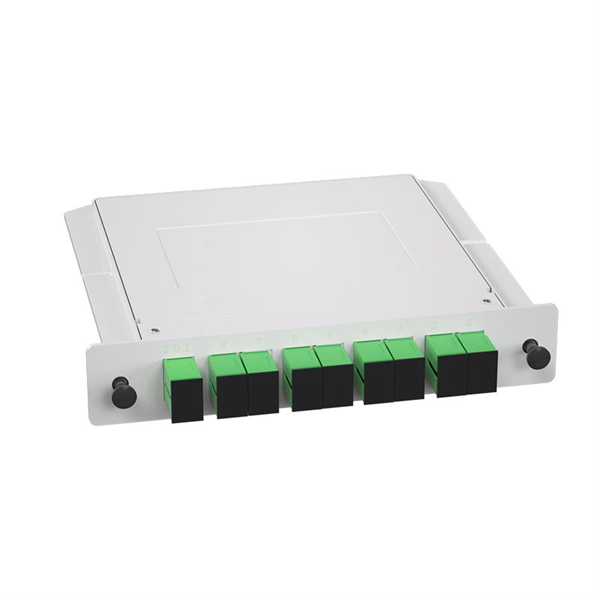
OMD-1800 is a bidirectional passive CWDM multiplexer/demultiplexer designed to transmit multiple optical channels over a single fiber. Supporting up to 18 wavelengths, it enables efficient point-to-point fiber utilization while maintaining low insertion loss and high channel. The Model 0201 OMD is a high capacity optical media shredder listed on the NSA/CSS EPL for CD destruction. It is also NSA/CSS EPL listed for DVD destruction through 2024 and meets DIN 66399 Level O-5 standards. The unit produces a residual particle size of 2. This optical. Everything you need to build an optical network from end-to-end. Thin-film filter and PLC based AWG for multiplexing, a full suite of components for optical amplification use, optomechanical or MEMS-based switches for protection or surveillance application, Tap PD for power monitoring and VOA for. The Model 0202 OMD Optical Media Destroyer is a system designed specifically for the destruction of Optical Media (CDs, DVDs). The system has been evaluated by the NSA, meets the NSA/CSS 04-02 Standards and is listed on the NSA Evaluated Products List. By audiobomber January 24 in Buy & Sell Audio and Computer Components This is the latest design and the currently-offered audiophile-grade fiber media converter (FMC), designed for Sonore by John Swenson to isolate network noise. Some erroneously refer to this model as a v3, but there is no v3.
[PDF]
A common test setup to evaluate Stressed Receiver Sensitivity involves measuring the Optical Modulation Amplitude (OMA) using a square wave, per the standard guidelines. Receiver sensitivity stands as a critical parameter impacting an optical transceiver's functionality. It denotes a module's capability to function in challenging environments and aids network operators in determining the system's maximum reach or link margin. These metrics provide insights into how well your transceivers perform under different conditions, ensuring seamless data transmission. Optical. Whether you're a network engineer validating new inventory or an integrator preparing for deployment, knowing how to test optical transceiver modules can save time, reduce failures, and ensure SLA compliance. Unchecked optical modules can cause: Testing ensures compliance with IEEE 802. 3 and MSA. In optical communication systems, sensitivity is a measure of how weak an input signal can get before the bit-error ratio (BER) exceeds some specified number. The standards body governing the application sets this specified BER. For example, SONET specifies that the BER must be 10 -10 or better. Why Fiber Optic Transceiver Testing is Important? Identify faults and failures: Transceiver testing helps in identifying any faults.
[PDF]